Toyota Yaris: Sfi System / Brake Switch "A"/"B" Signal Cross Coupled (P05042B)
DESCRIPTION
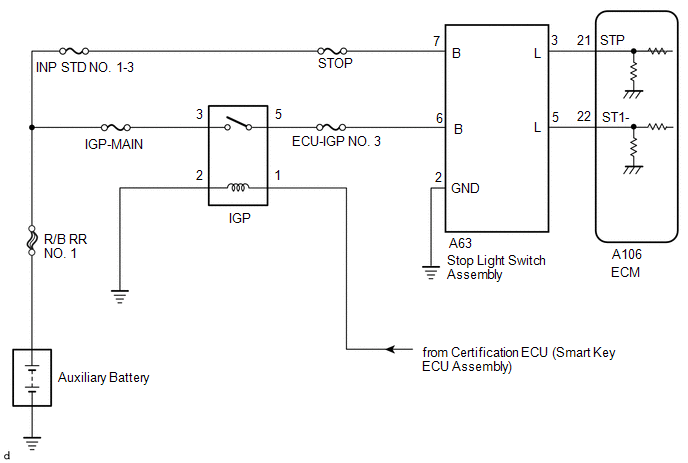
The stop light switch assembly is a duplex system that transmits two signals: STP and ST1-. These two signals are used by the ECM to monitor whether or not the brake system is working properly. If the signals, which indicate the brake pedal is being depressed and released, are detected simultaneously, the ECM interprets this as a malfunction in the stop light switch assembly and stores this DTC.
HINT:
The normal signal conditions are as shown in the table below.
| Signal (ECM Terminal) | Brake Pedal Released | In Transition | Brake Pedal Depressed |
|---|---|---|---|
| STP | OFF | ON | ON |
| ST1- | ON | ON | OFF |
- [OFF] denotes ground potential.
- [ON] denotes auxiliary battery potential (+B).
- On the GTS, Data List items Stop Light SW is ON when the brake pedal is depressed.
| DTC No. | Detection Item | DTC Detection Condition | Trouble Area | MIL | Note |
|---|---|---|---|---|---|
| P05042B | Brake Switch "A"/"B" Signal Cross Coupled | Conditions (a) and (b) continue for 0.5 seconds or more (1 trip detection logic): (a) Ignition switch to ON (b) STP signal OFF when ST1- signal OFF |
| - | SAE: P0504 |
WIRING DIAGRAM
CAUTION / NOTICE / HINT
NOTICE:
Inspect the fuses for circuits related to this system before performing the following procedure.
HINT:
- Read Freeze Frame Data using the GTS. The ECM records vehicle and driving condition information as Freeze Frame Data the moment a DTC is stored. When troubleshooting, Freeze Frame Data can help determine if the vehicle was moving or stationary, if the engine was warmed up or not, if the air fuel ratio was lean or rich, and other data from the time the malfunction occurred.
-
Stop light switch assembly conditions can be checked using the GTS.
- Connect the GTS to the DLC3.
- Turn the ignition switch to ON.
- Turn the GTS on.
- Enter the following menus: Powertrain / Engine / Data List / Stop Light SW.
-
Check the Data List indication when the brake pedal is depressed and released.
Brake Pedal Operation
Stop Light SW
Depressed
ON
Released
OFF
PROCEDURE
| 1. | CHECK TERMINAL VOLTAGE (POWER SOURCE OF STOP LIGHT SWITCH ASSEMBLY) |
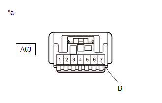
(a) Disconnect the stop light switch assembly connector.
| (b) Measure the voltage according to the value(s) in the table below. Standard Voltage:
|
|
| NG |
 | REPAIR OR REPLACE HARNESS OR CONNECTOR (STOP LIGHT SWITCH ASSEMBLY - AUXILIARY BATTERY) |
|

| 2. | CHECK TERMINAL VOLTAGE (POWER SOURCE OF STOP LIGHT SWITCH ASSEMBLY) |
(a) Disconnect the stop light switch assembly connector.
(b) Turn the ignition switch to ON.
| (c) Measure the voltage according to the value(s) in the table below. Standard Voltage:
|
|
| NG |
 | REPAIR OR REPLACE HARNESS OR CONNECTOR (STOP LIGHT SWITCH ASSEMBLY - IG2 D RELAY) |
|

| 3. | CHECK HARNESS AND CONNECTOR (STOP LIGHT SWITCH ASSEMBLY - BODY GROUND) |
(a) Disconnect the stop light switch assembly connector.
(b) Measure the resistance according to the value(s) in the table below.
Standard Resistance:
| Tester Connection | Condition | Specified Condition |
|---|---|---|
| A63-2(GND) - Body ground | Always | Below 1 Ω |
| NG |
 | REPAIR OR REPLACE HARNESS OR CONNECTOR |
|

| 4. | CHECK TERMINAL VOLTAGE (STP AND ST1- VOLTAGE) |
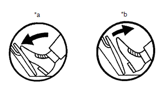
| *a | Brake Pedal Depressed |
| *b | Brake Pedal Released |
(a) Disconnect the ECM connector.
(b) Turn the ignition switch to ON.
(c) Measure the voltage according to the value(s) in the table below.
Standard Voltage:
| Tester Connection | Brake Pedal Operation | Specified Condition |
|---|---|---|
| A106-22(ST1-) - Body ground | Released | 7.5 to 14 V |
| Depressed | Below 1.5 V | |
| A106-21(STP) - Body ground | Released | Below 1.5 V |
| Depressed | 7.5 to 14 V |
| OK |
 | REPLACE ECM |
|

| 5. | CHECK HARNESS AND CONNECTOR (STOP LIGHT SWITCH ASSEMBLY - ECM) |
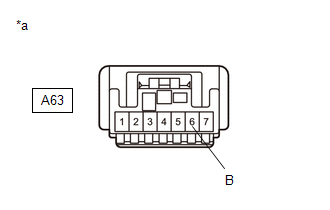
(a) Disconnect the stop light switch assembly connector.
(b) Disconnect the ECM connector.
(c) Measure the resistance according to the value(s) in the table below.
Standard Resistance:
| Tester Connection | Condition | Specified Condition |
|---|---|---|
| A63-5(L) - A106-22(ST1-) | Always | Below 1 Ω |
| A63-3(L) - A106-21(STP) | Always | Below 1 Ω |
| A63-5(L) or A106-22(ST1-) - Body ground and other terminals | Always | 10 kΩ or higher |
| A63-3(L) or A106-21(STP) - Body ground and other terminals | Always | 10 kΩ or higher |
| OK |
 | REPLACE STOP LIGHT SWITCH ASSEMBLY |
| NG |
 | REPAIR OR REPLACE HARNESS OR CONNECTOR (STOP LIGHT SWITCH ASSEMBLY - ECM) |
 Vehicle Speed Sensor "A" No Signal (P050031)
DESCRIPTION Vehicles, which are equipped with ABS (Anti-lock Brake System), detect the vehicle speed using the skid control ECU (brake actuator assembly) and speed sensor...
 Engine Oil Pressure Sensor/Switch "A" Circuit Short to Battery (P052012,P052014)
DESCRIPTION
The oil pressure sensor (engine oil pressure and temperature sensor) utilizes a semiconductor type pressure sensor that changes resistance in accordance with changes in pressure...
Other information:
Toyota Yaris XP210 (2020-2026) Owner's Manual: Cruise Control
With cruise control, you can set and automatically maintain any speed of more than about 16 mph (25 km/h). WARNING Do not use the cruise control under the following conditions Using the cruise control under the following conditions is dangerous and could result in loss of vehicle control...
Toyota Yaris XP210 (2020-2026) Reapir and Service Manual: Components
C..
Categories
- Manuals Home
- Toyota Yaris Owners Manual
- Toyota Yaris Service Manual
- Diagnostic Trouble Code Chart
- Adjustment
- Fuse Panel Description
- New on site
- Most important about car
Supplemental Restraint System (SRS) Precautions
The front and side supplemental restraint systems (SRS) include different types of air bags. Please verify the different types of air bags which are equipped on your vehicle by locating the “SRS AIRBAG” location indicators. These indicators are visible in the area where the air bags are installed.
The air bags are installed in the following locations:
The steering wheel hub (driver air bag) The front passenger dashboard (front passenger air bag) The outboard sides of the front seatbacks (side air bags) The front and rear window pillars, and the roof edge along both sides (curtain air bags)