Toyota Yaris: Sfi System / Engine Oil Pressure Sensor/Switch "A" Circuit Short to Battery (P052012,P052014)
DESCRIPTION
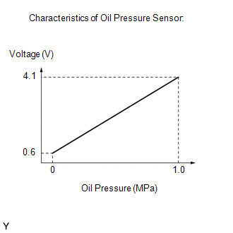
The oil pressure sensor (engine oil pressure and temperature sensor) utilizes a semiconductor type pressure sensor that changes resistance in accordance with changes in pressure. An internal electrical signal that varies with the change in resistance is amplified and sent to the ECM as the engine oil pressure signal.
| DTC No. | Detection Item | DTC Detection Condition | Trouble Area | MIL | Note |
|---|---|---|---|---|---|
| P052012 | Engine Oil Pressure Sensor/Switch "A" Circuit Short to Battery | The oil pressure sensor (engine oil pressure and temperature sensor) output voltage is higher than 4.495 V for 5 seconds or more (1 trip detection logic). |
| Comes on | SAE: P0523 |
| P052014 | Engine Oil Pressure Sensor/Switch "A" Circuit Short to Ground or Open | The oil pressure sensor (engine oil pressure and temperature sensor) output voltage is below 0.159 V for 5 seconds or more (1 trip detection logic). |
| Comes on | SAE: P0522 |
| DTC No. | Data List |
|---|---|
| P052012 | Engine Oil Pressure |
| P052014 |
MONITOR DESCRIPTION
The ECM calculates the engine oil pressure based on the output voltage of the oil pressure sensor (engine oil pressure and temperature sensor). If the signal output from the oil pressure sensor is outside of the specified range, the MIL is illuminated and a DTC is stored.
MONITOR STRATEGY
| Frequency of Operation | Continuous |
CONFIRMATION DRIVING PATTERN
- Connect the GTS to the DLC3.
- Turn the ignition switch to ON.
- Turn the GTS on.
- Clear the DTCs (even if no DTCs are stored, perform the clear DTC procedure).
- Turn the ignition switch off and wait for at least 30 seconds.
- Turn the ignition switch to ON.
- Turn the GTS on.
- Wait 10 seconds or more.
- Enter the following menus: Powertrain / Engine / Trouble Codes.
-
Read the pending DTCs.
HINT:
- If a pending DTC is output, the system is malfunctioning.
- If a pending DTC is not output, perform the following procedure.
- Enter the following menus: Powertrain / Engine / Utility / All Readiness.
- Input the DTC: P052012 or P052014.
-
Check the DTC judgment result.
GTS Display
Description
NORMAL
- DTC judgment completed
- System normal
ABNORMAL
- DTC judgment completed
- System abnormal
INCOMPLETE
- DTC judgment not completed
- Perform driving pattern after confirming DTC enabling conditions
HINT:
- If the judgment result is NORMAL, the system is normal.
- If the judgment result is ABNORMAL, the system is malfunctioning.
WIRING DIAGRAM
Production date from 2021/04 to 2021/07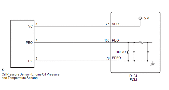 Production date from 2021/07
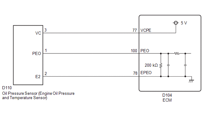
CAUTION / NOTICE / HINT
HINT:
Read Freeze Frame Data using the GTS. The ECM records vehicle and driving condition information as Freeze Frame Data the moment a DTC is stored. When troubleshooting, Freeze Frame Data can help determine if the vehicle was moving or stationary, if the engine was warmed up or not, if the air fuel ratio was lean or rich, and other data from the time the malfunction occurred.
PROCEDURE
| 1. | CHECK VEHICLE SPECIFICATION |
(a) Check the vehicle specification
| Result | Proceed to |
|---|---|
| Production date from 2021/04 to 2021/07 | A |
| Production date from 2021/07 | B |
| B |
 | GO TO STEP 4 |
|

| 2. | CHECK HARNESS AND CONNECTOR |
HINT:
Make sure that the connector is properly connected. If it is not, securely connect it and check for DTCs again.
(a) Disconnect the oil pressure sensor (engine oil pressure and temperature sensor) connector.
(b) Turn the ignition switch to ON.
| (c) Measure the voltage according to the value(s) in the table below. Standard Voltage:
|
|
(d) Turn the ignition switch off and wait for at least 30 seconds.
(e) Measure the resistance according to the value(s) in the table below.
Standard Resistance:
| Tester Connection | Condition | Specified Condition |
|---|---|---|
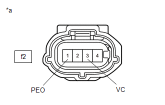
| f2-1(PEO) - f2-2(E2) | Ignition switch off | 190 to 210 kΩ |
| f2-2(E2) - Body ground | Always | Below 1 Ω |
| OK |
 | REPLACE OIL PRESSURE SENSOR (ENGINE OIL PRESSURE AND TEMPERATURE SENSOR) |
|

| 3. | CHECK HARNESS AND CONNECTOR (OIL PRESSURE SENSOR (ENGINE OIL PRESSURE AND TEMPERATURE SENSOR) - ECM) |
(a) Disconnect the oil pressure sensor (engine oil pressure and temperature sensor) connector.
(b) Disconnect the ECM connector.
(c) Measure the resistance according to the value(s) in the table below.
Standard Resistance:
| Tester Connection | Condition | Specified Condition |
|---|---|---|
| f2-2(E2) - D104-78(EPEO) | Always | Below 1 Ω |
| f2-1(PEO) - D104-100(PEO) | Always | Below 1 Ω |
| f2-3(VC) - D104-77(VCPE) | Always | Below 1 Ω |
| f2-2(E2) or D104-78(EPEO) - Body ground and other terminals | Always | 10 kΩ or higher |
| f2-1(PEO) or D104-100(PEO) - Body ground and other terminals | Always | 10 kΩ or higher |
| f2-3(VC) or D104-77(VCPE) - Body ground and other terminals | Always | 10 kΩ or higher |
| OK |
 | REPLACE ECM |
| NG |
 | REPAIR OR REPLACE HARNESS OR CONNECTOR |
| 4. | CHECK HARNESS AND CONNECTOR |
HINT:
Make sure that the connector is properly connected. If it is not, securely connect it and check for DTCs again.
(a) Disconnect the oil pressure sensor (engine oil pressure and temperature sensor) connector.
(b) Turn the ignition switch to ON.
| (c) Measure the voltage according to the value(s) in the table below. Standard Voltage:
|
|
(d) Turn the ignition switch off and wait for at least 30 seconds.
(e) Measure the resistance according to the value(s) in the table below.
Standard Resistance:
| Tester Connection | Condition | Specified Condition |
|---|---|---|
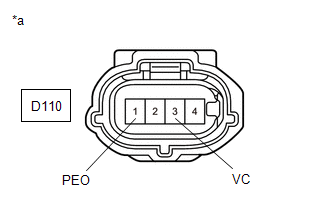
| D110-1(PEO) - D110-2(E2) | Ignition switch off | 190 to 210 kΩ |
| D110-2(E2) - Body ground | Always | Below 1 Ω |
| OK |
 | REPLACE OIL PRESSURE SENSOR (ENGINE OIL PRESSURE AND TEMPERATURE SENSOR) |
|

| 5. | CHECK HARNESS AND CONNECTOR (OIL PRESSURE SENSOR (ENGINE OIL PRESSURE AND TEMPERATURE SENSOR) - ECM) |
(a) Disconnect the oil pressure sensor (engine oil pressure and temperature sensor) connector.
(b) Disconnect the ECM connector.
(c) Measure the resistance according to the value(s) in the table below.
Standard Resistance:
| Tester Connection | Condition | Specified Condition |
|---|---|---|
| D110-2(E2) - D104-78(EPEO) | Always | Below 1 Ω |
| D110-1(PEO) - D104-100(PEO) | Always | Below 1 Ω |
| D110-3(VC) - D104-77(VCPE) | Always | Below 1 Ω |
| D110-2(E2) or D104-78(EPEO) - Body ground and other terminals | Always | 10 kΩ or higher |
| D110-1(PEO) or D104-100(PEO) - Body ground and other terminals | Always | 10 kΩ or higher |
| D110-3(VC) or D104-77(VCPE) - Body ground and other terminals | Always | 10 kΩ or higher |
| OK |
 | REPLACE ECM |
| NG |
 | REPAIR OR REPLACE HARNESS OR CONNECTOR |
 Brake Switch "A"/"B" Signal Cross Coupled (P05042B)
DESCRIPTION The stop light switch assembly is a duplex system that transmits two signals: STP and ST1-. These two signals are used by the ECM to monitor whether or not the brake system is working properly...
 Engine Oil Pressure Sensor/Switch "A" Signal Stuck High (P052024,P05202A)
DESCRIPTION Refer to DTC P052012. Click here
DTC No. Detection Item DTC Detection Condition Trouble Area MIL Note P052024 Engine Oil Pressure Sensor/Switch "A" Signal Stuck High The oil pressure sensor output voltage is higher than the threshold value (1 trip detection logic)...
Other information:
Toyota Yaris XP210 (2020-2026) Reapir and Service Manual: Inspection
INSPECTION PROCEDURE 1. INSPECT TURN SIGNAL SWITCH (a) Check the resistance. (1) Measure the resistance according to the value(s) in the table below. Standard Resistance: Light Control Switch Tester Connection Condition Specified Condition z6-7 (A) - z6-5 (EL) Light control switch in AUTO position Below 1 Ω z6-3 (T) - z6-5 (EL) Light control switch in tail position Below 1 Ω z6-12 (H) - z6-5 (EL) Light control switch in head position Below 1 Ω Dimmer Passing Switch Tester Connection Condition Specified Condition z6-11 (HF) - z6-5 (EL) Dimmer switch in high flash position Below 1 Ω z6-16 (HU) - z6-5 (EL) Dimmer switch in high position Below 1 Ω Fog Light Switch Tester Connection Condition Specified Condition z6-4 (B) - z6-5 (EL) Fog light switch in rear position Below 1 Ω z6-13 (BFG) - z6-5 (EL) Fog light switch in front position Below 1 Ω Turn Signal Switch Tester Connection Condition Specified Condition z6-8 (TR) - z6-5 (EL) Turn signal switch in neutral position 10 kΩ or higher z6-14 (TL) - z6-5 (EL) Turn signal switch in neutral position 10 kΩ or higher z6-8 (TR) - z6-5 (EL) Turn signal switch in right turn position Below 1 Ω z6-8 (TR) - z6-5 (EL) Turn signal switch in full right turn position Below 1 Ω z6-8 (TR) - z6-6 (CR) Turn signal switch in full right turn position Below 1 Ω z6-6 (CR) - z6-5 (EL) Turn signal switch in full right turn position Below 1 Ω z6-14 (TL) - z6-5 (EL) Turn signal switch in left turn position Below 1 Ω z6-14 (TL) - z6-5 (EL) Turn signal switch in full left turn position Below 1 Ω z6-14 (TL) - z6-6 (CR) Turn signal switch in full left turn position Below 1 Ω z6-6 (CR) - z6-5 (EL) Turn signal switch in full left turn position Below 1 Ω If the result is not as specified, replace the turn signal switch...
Toyota Yaris XP210 (2020-2026) Reapir and Service Manual: Removal
REMOVAL PROCEDURE 1. REMOVE RAIN SENSOR COVER (a) Disengage the claws and guide to remove the rain sensor cover. 2. REMOVE RAIN SENSOR (a) Release the stopper by pulling it out as shown in the illustration. *a Stopper Release Separate in this Direction (b) Separate the rain sensor from the windshield glass as shown in the illustration...
Categories
- Manuals Home
- Toyota Yaris Owners Manual
- Toyota Yaris Service Manual
- Headlights
- Diagnostic Trouble Code Chart
- G16e-gts (engine Mechanical)
- New on site
- Most important about car
Turning the Engine Off
Stop the vehicle completely. Manual transaxle: Shift into neutral and set the parking brake.Automatic transaxle: Shift the selector lever to the P position and set the parking brake.
Press the push button start to turn off the engine. The ignition position is off.