Toyota Yaris: Sfi System / Evaporative Emission System Purge Control Valve "A" Circuit Open (P044313)
DESCRIPTION
To reduce hydrocarbon (HC) emissions, evaporated fuel from the fuel tank is routed through a charcoal canister to the intake manifold for combustion in the cylinders.
The ECM changes the duty signals to the purge VSV (Vacuum Switching Valve for Purge Control) so that the intake amount of hydrocarbon (HC) emissions is appropriate for the driving conditions (engine load, engine speed, vehicle speed, etc.) after the engine is warmed up.
| DTC No. | Detection Item | DTC Detection Condition | Trouble Area | MIL | Note |
|---|---|---|---|---|---|
| P044313 | Evaporative Emission System Purge Control Valve "A" Circuit Open | Both of the following conditions (a) and (b) are met for 10 seconds or more (1 trip detection logic): (a) The purge VSV operation duty signal is 5 to 95%. (b) The target control value and actual control value do not match. |
| Comes on | SAE: P0443 |
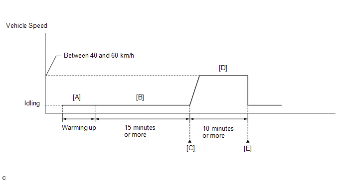
CONFIRMATION DRIVING PATTERN
- Connect the GTS to the DLC3.
- Turn the ignition switch to ON and turn the GTS on.
- Clear the DTCs (even if no DTCs are stored, perform the clear DTC procedure).
- Turn the ignition switch off and wait for at least 30 seconds.
- Turn the ignition switch to ON and turn the GTS on.
-
Start the engine and warm it up until the engine coolant temperature is 75°C (167°F) or higher [A].
HINT:
The A/C switch and all accessory switches should be off.
-
Idle the engine for 15 minutes or more [B].
HINT:
Check the EVAP (Purge) VSV item in the Data List. When the value of this item is between 5 and 95%, the judgment will be performed.
- Enter the following menus: Powertrain / Engine / Trouble Codes [C].
-
Read the pending DTCs.
HINT:
- If a pending DTC is output, the system is malfunctioning.
- If a pending DTC is not output, perform the following procedure.
- Enter the following menus: Powertrain / Engine / Utility / All Readiness.
- Input the DTC: P044313.
-
Check the DTC judgment result.
GTS Display
Description
NORMAL
- DTC judgment completed
- System normal
ABNORMAL
- DTC judgment completed
- System abnormal
INCOMPLETE
- DTC judgment not completed
- Perform driving pattern after confirming DTC enabling conditions
HINT:
- If the judgment result shows NORMAL, the system is normal.
- If the judgment result shows ABNORMAL, the system has a malfunction.
- If the judgment result shows INCOMPLETE, perform steps [D] and [E].
-
Drive the vehicle at a constant speed between 40 and 60 km/h (25 and 37 mph) for 10 minutes or more [D].
CAUTION:
When performing the confirmation driving pattern, obey all speed limits and traffic laws.
- Enter the following menus: Powertrain / Engine / Trouble Codes [E].
-
Read the pending DTCs.
HINT:
- If a pending DTC is output, the system is malfunctioning.
- If a pending DTC is not output, perform the following procedure.
- Enter the following menus: Powertrain / Engine / Utility / All Readiness.
- Input the DTC: P044313.
-
Check the DTC judgment result.
GTS Display
Description
NORMAL
- DTC judgment completed
- System normal
ABNORMAL
- DTC judgment completed
- System abnormal
INCOMPLETE
- DTC judgment not completed
- Perform driving pattern after confirming DTC enabling conditions
HINT:
- If the judgment result shows NORMAL, the system is normal.
- If the judgment result shows ABNORMAL, the system has a malfunction.
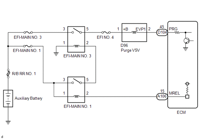
WIRING DIAGRAM
CAUTION / NOTICE / HINT
NOTICE:
Inspect the fuses of circuits related to this system before performing the following procedure.
HINT:
Read freeze frame data using the GTS. The ECM records vehicle and driving condition information as freeze frame data the moment a DTC is stored. When troubleshooting, freeze frame data can help determine if the vehicle was moving or stationary, if the engine was warmed up or not, if the air fuel ratio was lean or rich, and other data from the time the malfunction occurred.
PROCEDURE
| 1. | PERFORM ACTIVE TEST USING GTS (ACTIVATE THE EVAP PURGE VSV) |
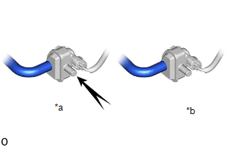
| *a | VSV is on |
| *b | VSV is off |
(a) Disconnect the fuel vapor feed hose (on the canister side) from the purge VSV.
(b) Start the engine.
(c) Enter the following menus.
Powertrain > Engine > Active Test| Tester Display |
|---|
| Activate the EVAP Purge VSV |
(d) When the purge VSV is operated using the GTS, check whether the port of the purge VSV applies suction to your finger.
OK:
| GTS Operation | Specified Condition |
|---|---|
| ON | Purge VSV port applies suction to finger |
| OFF | Purge VSV port applies no suction to finger |
HINT:
Jiggle the wire harness and connector to increase the likelihood of detecting malfunctions that do not always occur.
| OK |
 | CHECK FOR INTERMITTENT PROBLEMS |
|

| 2. | INSPECT PURGE VSV |
Click here

| NG |
 | REPLACE PURGE VSV |
|

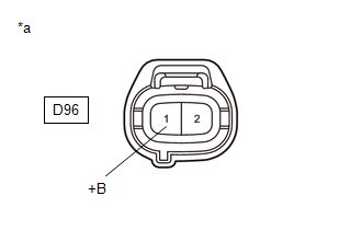
| 3. | CHECK TERMINAL VOLTAGE (POWER SOURCE OF PURGE VSV) |
(a) Disconnect the purge VSV connector.
(b) Turn the ignition switch to ON.
| (c) Measure the voltage according to the value(s) in the table below. Standard Voltage:
|
|
| NG |
 | GO TO STEP 5 |
|

| 4. | CHECK HARNESS AND CONNECTOR (PURGE VSV - ECM) |
(a) Disconnect the purge VSV connector.
(b) Disconnect the ECM connector.
(c) Measure the resistance according to the value(s) in the table below.
Standard Resistance:
| Tester Connection | Condition | Specified Condition |
|---|---|---|
| D96-2(EVP1) - D104-45(PRG) | Always | Below 1 Ω |
| D96-2(EVP1) or D104-45(PRG) - Body ground and other terminals | Always | 10 kΩ or higher |
| OK |
 | REPLACE ECM |
| NG |
 | REPAIR OR REPLACE HARNESS OR CONNECTOR |
| 5. | INSPECT EFI-MAIN NO. 3 RELAY |
Click here

| NG |
 | REPLACE EFI-MAIN NO. 3 RELAY |
|

| 6. | CHECK HARNESS AND CONNECTOR (POWER SOURCE OF EFI-MAIN NO. 3 RELAY) |
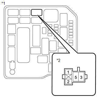
| (a) Remove the EFI-MAIN NO. 3 relay from the No. 1 engine room relay block assembly. |
|
(b) Measure the voltage according to the value(s) in the table below.
Standard Voltage:
| Tester Connection | Condition | Specified Condition |
|---|---|---|
| 3 (EFI-MAIN NO. 3 relay) - Body ground | Always | 11 to 14 V |
| NG |
 | REPAIR OR REPLACE HARNESS OR CONNECTOR (AUXILIARY BATTERY - EFI-MAIN NO. 3 RELAY) |
|

| 7. | CHECK HARNESS AND CONNECTOR (EFI-MAIN NO. 3 RELAY - BODY GROUND) |
(a) Remove the EFI-MAIN NO. 3 relay from the No. 1 engine room relay block assembly.
(b) Measure the resistance according to the value(s) in the table below.
Standard Resistance:
| Tester Connection | Condition | Specified Condition |
|---|---|---|
| 1 (EFI-MAIN NO. 3 relay) - Body ground | Always | Below 1 Ω |
| NG |
 | REPAIR OR REPLACE HARNESS OR CONNECTOR |
|

| 8. | CHECK HARNESS AND CONNECTOR (EFI-MAIN NO. 3 RELAY - PURGE VSV) |
(a) Remove the EFI-MAIN NO. 1 relay, EFI-MAIN NO. 3 relay and EDU relay from the No. 1 engine room relay block assembly.
HINT:
Remove the EFI-MAIN NO. 1 relay and EDU relay connected between the checked terminals as the coil inside the relay influences the measurement value.
(b) Disconnect the purge VSV connector.
(c) Measure the resistance according to the value(s) in the table below.
Standard Resistance:
| Tester Connection | Condition | Specified Condition |
|---|---|---|
| 5(EFI-MAIN NO. 3 relay) - D96-1(+B) | Always | Below 1 Ω |
| 5(EFI-MAIN NO. 3 relay) or D96-1(+B) - Body ground and other terminals | Always | 10 kΩ or higher |
| OK |
 | REPAIR OR REPLACE HARNESS OR CONNECTOR (EFI-MAIN NO. 1 RELAY - EFI-MAIN NO. 3 RELAY) |
| NG |
 | REPAIR OR REPLACE HARNESS OR CONNECTOR |
 Catalyst System Efficiency Below Threshold Bank 1 (P042000)
MONITOR DESCRIPTION The ECM uses air fuel ratio sensors mounted in front of and behind the Three-Way Catalytic Converter (TWC) to monitor its efficiency...
 Vehicle Speed Sensor "A" No Signal (P050031)
DESCRIPTION Vehicles, which are equipped with ABS (Anti-lock Brake System), detect the vehicle speed using the skid control ECU (brake actuator assembly) and speed sensor...
Other information:
Toyota Yaris XP210 (2020-2026) Reapir and Service Manual: Installation
INSTALLATION PROCEDURE 1. INSTALL GENERATOR WITH REGULATOR ASSEMBLY (a) Temporarily install the generator with regulator assembly. (b) Using an E8 "TORX" socket wrench, install the 2 stud bolts. Torque: 9.8 N·m {100 kgf·cm, 87 in·lbf} (c) Install the bolt...
Toyota Yaris XP210 (2020-2026) Reapir and Service Manual: Installation
INSTALLATION PROCEDURE 1. INSTALL HOLE PLUG (a) Install the 8 hole plugs to the rear suspension member sub-assembly. 2. INSTALL REAR SUSPENSION MEMBER HOLE COVER (a) Install the 4 rear suspension member hole covers to the rear suspension member sub-assembly...
Categories
- Manuals Home
- Toyota Yaris Owners Manual
- Toyota Yaris Service Manual
- Headlights
- To Set Speed
- Engine Start Function When Key Battery is Dead
- New on site
- Most important about car
Fuel Gauge
The fuel gauge shows approximately how much fuel is remaining in the tank when the ignition is switched ON. We recommend keeping the tank over 1/4 full.
