Toyota Yaris: Sfi System / Catalyst System Efficiency Below Threshold Bank 1 (P042000)
MONITOR DESCRIPTION
The ECM uses air fuel ratio sensors mounted in front of and behind the Three-Way Catalytic Converter (TWC) to monitor its efficiency.
The first sensor, the air fuel ratio sensor (sensor 1), sends pre-catalyst information to the ECM. The second sensor, the air fuel ratio sensor (sensor 2), sends post-catalyst information to the ECM.
In order to detect any deterioration in the three-way catalytic converter, the ECM calculates the oxygen storage capacity of the three-way catalytic converter. This calculation is based on the output current of the air fuel ratio sensor (sensor 2) while performing active air fuel ratio control.
The oxygen storage capacity value is an indication of the oxygen storage capacity of the three-way catalytic converter. When the vehicle is being driven with a warm engine, active air fuel ratio control is performed for approximately 30 seconds. When it is performed, the ECM deliberately sets the air fuel ratio to lean or rich levels. If the cycle of the waveform for the air fuel ratio sensor (sensor 2) is long, the oxygen storage capacity is great. There is a direct correlation between the air fuel ratio sensor (sensor 2) and the oxygen storage capacity of the three-way catalytic converter.
The ECM uses the oxygen storage capacity value to determine the state of the three-way catalytic converter. If any deterioration has occurred, the ECM will illuminate the MIL and store a DTC.
This system determines the deterioration of the entire catalyst system (including the front and rear catalysts), by using the oxygen storage capacity value of the front catalyst, that is more sensitive than the rear catalyst, as the representative value. Therefore, be sure to replace the front and rear catalysts together when catalyst replacement is necessary.
| DTC No. | Detection Item | DTC Detection Condition | Trouble Area | MIL | Note |
|---|---|---|---|---|---|
| P042000 | Catalyst System Efficiency Below Threshold Bank 1 | The oxygen storage capacity value is less than the standard value under active air fuel ratio control (1 trip detection logic). |
| Comes on | SAE: P0420 |
CATALYST LOCATION
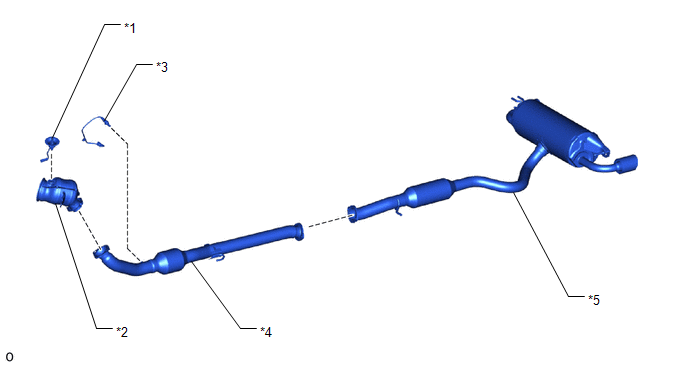
| *1 | Exhaust Manifold (TWC: Front Catalyst) | *2 | Front Exhaust Pipe Assembly (TWC: Rear Catalyst) |
| *3 | Tail Exhaust Pipe Assembly | *4 | Air Fuel Ratio Sensor (Sensor 1) |
| *5 | Air Fuel Ratio Sensor (Sensor 2) | - | - |
NOTICE:
When replacing the exhaust manifold (*1) and the front exhaust pipe assembly (*2) in order to replace the three-way catalytic converter, it is not necessary to replace the air fuel ratio sensor (sensor 1) (*4) and the air fuel ratio sensor (sensor 2) (*5).
MONITOR STRATEGY
| Required Sensors/Components (Main) | Air fuel ratio sensor (sensor 1) Air fuel ratio sensor (sensor 2) |
| Required Sensors/Components (Related) | Intake air temperature sensor Mass air flow meter sub-assembly Crankshaft position sensor Engine coolant temperature sensor |
| Frequency of Operation | Once per driving cycle |
TYPICAL ENABLING CONDITIONS
| Auxiliary battery voltage | 11 V or higher |
| Intake air temperature | -10°C (14°F) or higher |
| Engine coolant temperature | 75°C (167°F) or higher |
| Atmospheric pressure | 76 kPa(abs) [11 psi(abs)] or higher |
| Idling | Off |
| Engine speed | Less than 3200 rpm |
| Air fuel ratio sensor (sensor 1) status | Activated |
| Fuel system status | Closed loop |
| Engine load | 10% or higher, and less than 140% |
| All of the following conditions are met | 1, 2 and 3 |
| 1. Mass air flow | 2.9 gm/sec or more, and less than 60 gm/sec |
| 2. Front catalyst temperature (estimated) | 500°C (932°F) or higher, and below 820°C (1508°F) |
| 3. Rear catalyst temperature (estimated) | 270°C (518°F) or higher, and below 700°C (1292°F) |
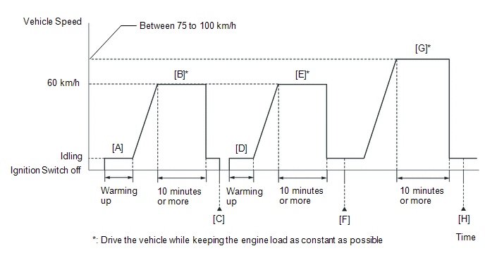
CONFIRMATION DRIVING PATTERN
HINT:
Performing this confirmation driving pattern will activate the catalyst efficiency monitor. This is very useful for verifying the completion of a repair.
- Connect the GTS to the DLC3.
- Turn the ignition switch to ON.
- Turn the GTS on.
- Clear the DTCs (even if no DTCs are stored, perform the clear DTC procedure).
- Turn the ignition switch off and wait for at least 30 seconds.
- Turn the ignition switch to ON.
- Turn the GTS on.
-
Start the engine and warm it up until the engine coolant temperature is 75°C (167°F) or higher with the shift lever in neutral [A].
HINT:
In order to keep the idle stable, turn the A/C and all other electric loads off and do not perform any shift operations.
-
Drive the vehicle at approximately 60 km/h (37 mph) for 10 minutes or more [B].
CAUTION:
When performing the confirmation driving pattern, obey all speed limits and traffic laws.
HINT:
Drive the vehicle while keeping the engine load as constant as possible.
- Turn the ignition switch off and wait for at least 30 seconds [C].
- Turn the ignition switch to ON.
- Turn the GTS on.
- Start the engine and warm it up until the engine coolant temperature is 75°C (167°F) or higher [D].
-
Drive the vehicle at approximately 60 km/h (37 mph) for 10 minutes or more [E].
CAUTION:
When performing the confirmation driving pattern, obey all speed limits and traffic laws.
HINT:
Drive the vehicle while keeping the engine load as constant as possible.
- Enter the following menus: Powertrain / Engine / Trouble Codes [F].
-
Read the pending DTCs.
HINT:
- If a pending DTC is output, the system is malfunctioning.
- If a pending DTC is not output, perform the following procedure.
- Enter the following menus: Powertrain / Engine / Utility / All Readiness.
- Input the DTC: P042000.
-
Check the DTC judgment result.
GTS Display
Description
NORMAL
- DTC judgment completed
- System normal
ABNORMAL
- DTC judgment completed
- System abnormal
INCOMPLETE
- DTC judgment not completed
- Perform driving pattern after confirming DTC enabling conditions
HINT:
- If the judgment result is NORMAL, the system is normal.
- If the judgment result is ABNORMAL, the system has a malfunction.
- If the judgment result is INCOMPLETE, perform the following procedure.
-
Drive the vehicle at a speed between 75 and 100 km/h (47 and 62 mph) for 10 minutes or more [G].
CAUTION:
When performing the confirmation driving pattern, obey all speed limits and traffic laws.
HINT:
Drive the vehicle while keeping the engine load as constant as possible.
- Enter the following menus: Powertrain / Engine / Trouble Codes [H].
-
Read the pending DTCs.
HINT:
- If a pending DTC is output, the system is malfunctioning.
- If a pending DTC is not output, perform the following procedure.
- Enter the following menus: Powertrain / Engine / Utility / All Readiness.
- Input the DTC: P042000.
-
Check the DTC judgment result.
GTS Display
Description
NORMAL
- DTC judgment completed
- System normal
ABNORMAL
- DTC judgment completed
- System abnormal
INCOMPLETE
- DTC judgment not completed
- Perform driving pattern after confirming DTC enabling conditions
HINT:
- If the judgment result is NORMAL, the system is normal.
- If the judgment result is ABNORMAL, the system is malfunctioning.
CAUTION / NOTICE / HINT
HINT:
- If a malfunction cannot be found when troubleshooting DTC P042000, a lean or rich abnormality may be the cause. Perform troubleshooting by following the inspection procedure for P017100 (System Too Lean) and P017200 (System Too Rich).
- Sensor 1 refers to the sensor closest to the engine assembly.
- Sensor 2 refers to the sensor farthest away from the engine assembly.
- Read Freeze Frame Data using the GTS. The ECM records vehicle and driving condition information as Freeze Frame Data the moment a DTC is stored. When troubleshooting, Freeze Frame Data can help determine if the vehicle was moving or stationary, if the engine was warmed up or not, if the air fuel ratio was lean or rich, and other data from the time the malfunction occurred.
PROCEDURE
| 1. | CHECK ANY OTHER DTCS OUTPUT (IN ADDITION TO DTC P042000) |
(a) Read the DTCs.
Powertrain > Engine > Trouble Codes| Result | Proceed to |
|---|---|
| P042000 and other DTCs are output | A |
| P042000 is output | B |
HINT:
If any DTCs other than P042000 are output, troubleshoot those DTCs first.
| A |
 | GO TO DTC CHART |
|

| 2. | PERFORM ACTIVE TEST USING GTS (CONTROL THE INJECTION VOLUME FOR A/F SENSOR) |
(a) Start the engine and warm it up until the engine coolant temperature is 75°C (167°F) or higher.
(b) Warm up the air fuel ratio sensors at an engine speed of 2500 rpm for 90 seconds.
(c) Enter the following menus.
Powertrain > Engine > Active Test| Active Test Display |
|---|
| Control the Injection Volume for A/F Sensor |
| Data List Display |
|---|
| Coolant Temperature |
| Injection Volume |
| A/F (O2) Sensor Current B1S1 |
| A/F (O2) Sensor Current B1S2 |
HINT:
- The Active Test "Control the Injection Volume for A/F Sensor" can be used to lower the fuel injection volume by 12.5% or increase the injection volume by 12.5%.
- The air fuel ratio sensor (sensor 1) is displayed as A/F (O2) Sensor Current B1S1, and the air fuel ratio sensor (sensor 2) is displayed as A/F (O2) Sensor Current B1S2 on the GTS.
- The air fuel ratio sensor (sensor 1) has an output delay of a few seconds and the air fuel ratio sensor (sensor 2) has a maximum output delay of approximately 20 seconds.
- If the sensor output current does not change (almost no reaction) while performing the Active Test, the sensor may be malfunctioning.
Standard:
| GTS Display (Sensor) | Injection Volume | Status | Current |
|---|---|---|---|
| A/F (O2) Sensor Current B1S1 (Air fuel ratio (sensor 1)) | 12.5% | Rich | Below -0.075 mA |
| -12.5% | Lean | Higher than 0.037 mA | |
| A/F (O2) Sensor Current B1S2 (Air fuel ratio (sensor 2)) | 12.5% | Rich | Below -0.86 mA |
| -12.5% | Lean | Higher than 0.33 mA |
| Status A/F (O2) Sensor Current B1S1 | Status A/F (O2) Sensor Current B1S2 | Actual air fuel ratio, air fuel ratio sensor (sensor 1) and air fuel ratio sensor (sensor 2) condition | Main Suspected Trouble Area | Proceed to |
|---|---|---|---|---|
| Lean/Rich | Lean/Rich | Normal |
| A |
| Lean | Lean/Rich | Air fuel ratio sensor (sensor 1) malfunction |
| B |
| Rich | Lean/Rich | Air fuel ratio sensor (sensor 1) malfunction |
| B |
| Lean/Rich | Lean | Air fuel ratio sensor (sensor 2) malfunction |
| C |
| Lean/Rich | Rich | Air fuel ratio sensor (sensor 2) malfunction |
| C |
| Lean | Lean | Actual air fuel ratio lean |
| D |
| Rich | Rich | Actual air fuel ratio rich |
| D |
- Lean: During the Control the Injection Volume for A/F Sensor Active Test, the air fuel ratio sensor (sensor 1) output current (A/F (O2) Sensor Current B1S1) is consistently higher than 0.037 mA, and the air fuel ratio sensor (sensor 2) output current (A/F (O2) Sensor Current B1S2) is consistently higher than 0.33 mA.
- Rich: During the Control the Injection Volume for A/F Sensor Active Test, the air fuel ratio sensor (sensor 1) output current (A/F (O2) Sensor Current B1S1) is consistently below -0.075 mA, and the air fuel ratio sensor (sensor 2) output current (A/F (O2) Sensor Current B1S2) is consistently below -0.86 mA.
- Lean/Rich: During the Control the Injection Volume for A/F Sensor Active Test, the output current of the air fuel ratio sensor (sensor 1) or air fuel ratio sensor (sensor 2) alternate correctly.
HINT:
Refer to "Data List / Active Test" [A/F (O2) Sensor Current B1S1, A/F (O2) Sensor Current B1S2].
Click here

| B |
 | GO TO STEP 4 |
| C |
 | GO TO STEP 5 |
| D |
 | GO TO STEP 7 |
|

| 3. | CHECK FOR EXHAUST GAS LEAK |
(a) Check for exhaust gas leaks.
OK:
No gas leaks in exhaust system.
| OK |
 | GO TO STEP 28 |
| NG |
 | GO TO STEP 25 |
| 4. | REPLACE AIR FUEL RATIO SENSOR (SENSOR 1) |
HINT:
Click here

Perform "Inspection After Repair" after replacing the air fuel ratio sensor (sensor 1).
Click here

| NEXT |
 | GO TO STEP 26 |
| 5. | CHECK FOR EXHAUST GAS LEAK |
(a) Check for exhaust gas leaks.
OK:
No gas leaks in exhaust system.
| NG |
 | GO TO STEP 25 |
|

| 6. | REPLACE AIR FUEL RATIO SENSOR (SENSOR 2) |
HINT:
Click here

Perform "Inspection After Repair" after replacing the air fuel ratio sensor (sensor 2).
Click here

| NEXT |
 | GO TO STEP 26 |
| 7. | CHECK FOR EXHAUST GAS LEAK |
(a) Check for exhaust gas leaks.
OK:
No gas leaks in exhaust system.
| NG |
 | GO TO STEP 25 |
|

| 8. | CHECK PCV VALVE AND HOSE CONNECTIONS |
(a) Check the PCV hose connections.
(b) Check the PCV valve.
Click here

OK:
PCV hose and PCV valve are connected correctly and are not damaged.
| NG |
 | REPAIR OR REPLACE PCV VALVE OR HOSE |
|

| 9. | CHECK INTAKE SYSTEM |
(a) Check the intake system for vacuum leaks.
Click here

OK:
No leaks in intake system.
| NG |
 | REPAIR OR REPLACE INTAKE SYSTEM |
|

| 10. | READ VALUE USING GTS (COOLANT TEMPERATURE) |
(a) Read the Data List twice, when the engine is both cold and warmed up.
Powertrain > Engine > Data List| Tester Display |
|---|
| Coolant Temperature |
Standard:
| GTS Display | Condition | Specified Condition |
|---|---|---|
| Coolant Temperature | Cold engine | Same as ambient air temperature |
| Warm engine | Between 75 and 100°C (167 and 212°F) |
| NG |
 | REPLACE ENGINE COOLANT TEMPERATURE SENSOR |
|

| 11. | INSPECT MASS AIR FLOW METER SUB-ASSEMBLY |
Click here

| NG |
 | GO TO STEP 17 |
|

| 12. | CHECK FUEL PRESSURE (FOR LOW PRESSURE SIDE) |
Click here

| NG |
 | GO TO STEP 24 |
|

| 13. | CHECK FUEL PRESSURE (FOR HIGH PRESSURE SIDE) |
Click here

| NG |
 | GO TO STEP 24 |
|

| 14. | INSPECT IGNITION SYSTEM |
Click here

HINT:
If the spark plugs or ignition system malfunctions, engine misfire may occur. The misfire count can be read using the GTS. Enter the following menus: Powertrain / Engine / Data List / Misfire Count Cylinder #1 to Misfire Count Cylinder #3.
| NG |
 | REPAIR OR REPLACE IGNITION SYSTEM |
|

| 15. | INSPECT PORT FUEL INJECTOR ASSEMBLY |
(a) Inspect the port fuel injector assembly (whether fuel volume is high or low, and whether injection pattern is poor).
Click here

HINT:
Perform "Inspection After Repair" after replacing the port fuel injector assembly.
Click here

| NG |
 | REPLACE PORT FUEL INJECTOR ASSEMBLY |
|

| 16. | INSPECT DIRECT FUEL INJECTOR ASSEMBLY |
Click here

HINT:
Perform "Inspection After Repair" after replacing the direct fuel injector assembly.
Click here

| NG |
 | REPLACE DIRECT FUEL INJECTOR ASSEMBLY |
|

| 17. | CHECK HARNESS AND CONNECTOR (MASS AIR FLOW METER SUB-ASSEMBLY CONNECTOR CONNECTION) |
(a) Check the connection and terminal contact pressure of connectors and wire harnesses between the mass air flow meter sub-assembly and ECM.
Click here

HINT:
Repair any problems.
|

| 18. | CLEAR DTC |
(a) Clear the DTCs.
Powertrain > Engine > Clear DTCs(b) Turn the ignition switch off and wait for at least 30 seconds.
|

| 19. | CHECK WHETHER DTC OUTPUT RECURS (DTC P042000) |
(a) Drive the vehicle in accordance with the driving pattern described in Confirmation Driving Pattern.
(b) Read the DTCs.
Powertrain > Engine > Trouble Codes| Result | Proceed to |
|---|---|
| DTCs are not output | A |
| P042000 is output | B |
| A |
 | END |
|

| 20. | CHECK HARNESS AND CONNECTOR (MASS AIR FLOW METER SUB-ASSEMBLY - ECM) |
(a) Disconnect the mass air flow meter sub-assembly connector.
(b) Disconnect the ECM connector.
(c) Measure the resistance according to the value(s) in the table below.
Standard Resistance:
| Tester Connection | Condition | Specified Condition |
|---|---|---|
| D23-3(VCC) - D104-84(VCVG) | Always | Below 1 Ω |
| D23-1(FG) - D104-107(VG) | Always | Below 1 Ω |
| D23-2(E2G) - D104-83(E2G) | Always | Below 1 Ω |
| D23-3(VCC) or D104-84(VCVG) - Body ground and other terminals | Always | 10 kΩ or higher |
| D23-1(FG) or D104-107(VG) - Body ground and other terminals | Always | 10 kΩ or higher |
| D23-2(E2G) or D104-83(E2G) - Body ground and other terminals | Always | 10 kΩ or higher |
| NG |
 | REPAIR OR REPLACE HARNESS OR CONNECTOR |
|

| 21. | REPLACE MASS AIR FLOW METER SUB-ASSEMBLY |
HINT:
-
Click here

- If the result of the inspection performed in steps 15 (READ VALUE USING GTS (MASS AIR FLOW SENSOR)) indicated no problem, proceed to the next step without replacing the mass air flow meter sub-assembly.
-
Perform "Inspection After Repair" after replacing the mass air flow meter sub-assembly.
Click here

|

| 22. | CLEAR DTC |
(a) Clear the DTCs.
Powertrain > Engine > Clear DTCs(b) Turn the ignition switch off and wait for at least 30 seconds.
|

| 23. | CONFIRM WHETHER MALFUNCTION HAS BEEN SUCCESSFULLY REPAIRED |
(a) Drive the vehicle in accordance with the driving pattern described in Confirmation Driving Pattern.
(b) Read the DTCs.
Powertrain > Engine > Trouble Codes| Result | Proceed to |
|---|---|
| DTCs are not output | A |
| P042000 is output | B |
| A |
 | END |
| B |
 | REPLACE ECM |
| 24. | CHECK FUEL LINE |
(a) Check the fuel lines for leaks or blockage.
| OK |
 | GO TO FUEL PUMP CONTROL CIRCUIT |
| NG |
 | REPAIR OR REPLACE FUEL SYSTEM |
| 25. | REPAIR OR REPLACE EXHAUST SYSTEM |
HINT:
Perform "Inspection After Repair" after repairing or replacing the exhaust system.
Click here

|

| 26. | CLEAR DTC |
(a) Clear the DTCs.
Powertrain > Engine > Clear DTCs(b) Turn the ignition switch off and wait for at least 30 seconds.
|

| 27. | CONFIRM WHETHER MALFUNCTION HAS BEEN SUCCESSFULLY REPAIRED |
(a) Drive the vehicle in accordance with the driving pattern described in Confirmation Driving Pattern.
(b) Read the DTCs.
Powertrain > Engine > Trouble Codes| Result | Proceed to |
|---|---|
| DTCs are not output | A |
| P042000 is output | B |
| A |
 | END |
|

| 28. | REPLACE EXHAUST MANIFOLD (TWC: FRONT CATALYST) AND FRONT EXHAUST PIPE ASSEMBLY (TWC: REAR CATALYST) |
NOTICE:
When replacing the exhaust manifold and the front exhaust pipe assembly in order to replace the three-way catalytic converter, it is not necessary to replace the air fuel ratio sensor (sensor 1) and the air fuel ratio sensor (sensor 2).
HINT:
Confirm the replacement parts, referring to the illustration in the Catalyst Location.
(a) Replace the exhaust manifold (TWC: Front catalyst).
Click here

(b) Replace the front exhaust pipe assembly (TWC: Rear catalyst).
Click here

| NEXT |
 | END |
 Camshaft Position Sensor "B" Bank 1 Signal Stuck in Range (P03652A,P036531)
DESCRIPTION Refer to DTC P036511. Click here
DTC No. Detection Item DTC Detection Condition Trouble Area MIL Note P03652A Camshaft Position Sensor "B" Bank 1 Signal Stuck in Range No camshaft position sensor (for exhaust camshaft) signal to ECM while engine cranking (1 trip detection logic)...
 Evaporative Emission System Purge Control Valve "A" Circuit Open (P044313)
DESCRIPTION To reduce hydrocarbon (HC) emissions, evaporated fuel from the fuel tank is routed through a charcoal canister to the intake manifold for combustion in the cylinders...
Other information:
Toyota Yaris XP210 (2020-2026) Reapir and Service Manual: Turbocharger Noise
DESCRIPTION HINT: Turbocharger noise is classified into two types. These are whistling sound and chattering sound. During troubleshooting, first determine the type of noise. Type of Abnormal Noise Outline of Abnormal Noise Major Trouble Area Whistling sound (airflow sound) The whistling sound volume and pitch are proportional to the turbocharger or engine speed...
Toyota Yaris XP210 (2020-2026) Reapir and Service Manual: Installation
INSTALLATION CAUTION / NOTICE / HINT NOTICE: After performing the update ECU security key procedure, make sure to perform the initialization procedure for when the cable has been disconnected and reconnected to the negative (-) auxiliary battery terminal...
Categories
- Manuals Home
- Toyota Yaris Owners Manual
- Toyota Yaris Service Manual
- Brake System Control Module "A" System Voltage System Voltage Low (C137BA2)
- To Set Speed
- Power Integration No.1 System Missing Message (B235287,B235587,B235787-B235987)
- New on site
- Most important about car
Fuel-Filler Lid and Cap
WARNING
When removing the fuel-filler cap, loosen the cap slightly and wait for any hissing to stop, then remove it
Fuel spray is dangerous. Fuel can burn skin and eyes and cause illness if ingested. Fuel spray is released when there is pressure in the fuel tank and the fuel-filler cap is removed too quickly.