Toyota Yaris: Sfi System / Camshaft Position Sensor "B" Bank 1 Signal Stuck in Range (P03652A,P036531)
DESCRIPTION
Refer to DTC P036511.
Click here

| DTC No. | Detection Item | DTC Detection Condition | Trouble Area | MIL | Note |
|---|---|---|---|---|---|
| P03652A | Camshaft Position Sensor "B" Bank 1 Signal Stuck in Range | No camshaft position sensor (for exhaust camshaft) signal to ECM while engine cranking (1 trip detection logic). |
| Comes on | SAE: P0365 |
| P036531 | Camshaft Position Sensor "B" Bank 1 No Signal | No camshaft position sensor (for exhaust camshaft) signal for 5 seconds at an engine speed of 600 rpm or higher (1 trip detection logic). * |
| Comes on | SAE: P0365 |
*: When the engine is being stopped or started automatically by stop and start system control, the ECM does not monitor the camshaft position sensor signal.
-
Reference: Inspection using an oscilloscope.
Click here

MONITOR DESCRIPTION
If no pulse signal is transmitted by the camshaft position sensor (for exhaust camshaft) despite the camshaft rotating, or the rotation of the camshaft and the crankshaft is not synchronized, the ECM interprets this as a malfunction of the sensor.
MONITOR STRATEGY
| Required Sensors/Components (Main) | Camshaft position sensor (for exhaust camshaft) |
| Required Sensors/Components (Related) | Crankshaft position sensor |
| Frequency of Operation | Continuous |
CONFIRMATION DRIVING PATTERN
- Connect the GTS to the DLC3.
- Turn the ignition switch to ON.
- Turn the GTS on.
- Clear the DTCs (even if no DTCs are stored, perform the clear DTC procedure).
- Turn the ignition switch off and wait for at least 30 seconds.
- Start the engine [A].
- Idle the engine for 10 seconds or more [B].
- Turn the GTS on.
- Enter the following menus: Powertrain / Engine / Trouble Codes [C].
-
Read the pending DTCs.
HINT:
- If a pending DTC is output, the system is malfunctioning.
- If a pending DTC is not output, perform the following procedure.
- Enter the following menus: Powertrain / Engine / Utility / All Readiness.
- Input the DTC: P03652A or P036531.
-
Check the DTC judgment result.
GTS Display
Description
NORMAL
- DTC judgment completed
- System normal
ABNORMAL
- DTC judgment completed
- System abnormal
INCOMPLETE
- DTC judgment not completed
- Perform driving pattern after confirming DTC enabling conditions
HINT:
- If the judgment result is NORMAL, the system is normal.
- If the judgment result is ABNORMAL, the system is malfunctioning.
- If the judgment result is INCOMPLETE, perform steps [B] through [C] again.
WIRING DIAGRAM
Refer to DTC P036511.
Click here

CAUTION / NOTICE / HINT
HINT:
- Read Freeze Frame Data using the GTS. The ECM records vehicle and driving condition information as Freeze Frame Data the moment a DTC is stored. When troubleshooting, Freeze Frame Data can help determine if the vehicle was moving or stationary, if the engine was warmed up or not, if the air fuel ratio was lean or rich, and other data from the time the malfunction occurred.
- If no problem is found through this diagnostic troubleshooting procedure, there may be a mechanical problem with the engine.
PROCEDURE
| 1. | CHECK HARNESS AND CONNECTOR |
HINT:
Make sure that the connector is properly connected. If it is not, securely connect it and check for DTCs again.
(a) Disconnect the camshaft position sensor (for exhaust camshaft) connector.
(b) Turn the ignition switch to ON.
| (c) Measure the voltage according to the value(s) in the table below. Standard Voltage:
|
|
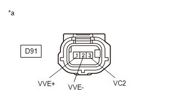
(d) Turn the ignition switch off and wait for at least 30 seconds.
(e) Measure the resistance according to the value(s) in the table below.
Standard Resistance:
| Tester Connection | Condition | Specified Condition |
|---|---|---|
| D91-3(VC2) - D91-1(VVE+) | Ignition switch off | 1.425 to 1.575 kΩ |
| D91-2(VVE-) - Body ground | Always | Below 1 Ω |
| NG |
 | GO TO STEP 4 |
|

| 2. | CHECK SENSOR INSTALLATION AND CONDUCT VISUAL INSPECTION (CAMSHAFT POSITION SENSOR (FOR EXHAUST CAMSHAFT)) |
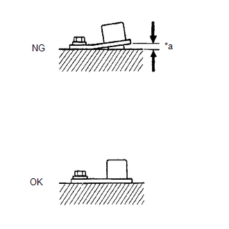
| *a | Clearance |
(a) Visually check the camshaft position sensor (for exhaust camshaft) for damage.
(b) Check the camshaft position sensor (for exhaust camshaft) installation condition.
OK:
The camshaft position sensor (for exhaust camshaft) does not have any damage and is installed properly.
| NG |
 | SECURELY REINSTALL CAMSHAFT POSITION SENSOR (FOR EXHAUST CAMSHAFT) |
|

| 3. | INSPECT EXHAUST CAMSHAFT (TIMING ROTOR) |
(a) Check the timing rotor of the exhaust camshaft.
OK:
Camshaft timing rotor does not have any cracks or deformation.
HINT:
Perform "Inspection After Repair" after replacing the exhaust camshaft.
Click here

| OK |
 | REPLACE CAMSHAFT POSITION SENSOR (FOR EXHAUST CAMSHAFT) |
| NG |
 | REPLACE EXHAUST CAMSHAFT |
| 4. | CHECK HARNESS AND CONNECTOR (CAMSHAFT POSITION SENSOR (FOR EXHAUST CAMSHAFT) - ECM) |
(a) Disconnect the camshaft position sensor (for exhaust camshaft) connector.
(b) Disconnect the ECM connector.
(c) Measure the resistance according to the value(s) in the table below.
Standard Resistance:
| Tester Connection | Condition | Specified Condition |
|---|---|---|
| D91-1(VVE+) - D104-91(EV1+) | Always | Below 1 Ω |
| D91-2(VVE-) - D104-114(EV1-) | Always | Below 1 Ω |
| D91-3(VC2) - D104-113(VCE1) | Always | Below 1 Ω |
| D91-1(VVE+) or D104-91(EV1+) - Body ground and other terminals | Always | 10 kΩ or higher |
| D91-2(VVE-) or D104-114(EV1-) - Body ground and other terminals | Always | 10 kΩ or higher |
| D91-3(VC2) or D104-113(VCE1) - Body ground and other terminals | Always | 10 kΩ or higher |
| OK |
 | REPLACE ECM |
| NG |
 | REPAIR OR REPLACE HARNESS OR CONNECTOR |
 Camshaft Position Sensor "B" Bank 1 Circuit Short to Ground (P036511,P036515)
DESCRIPTION The camshaft position sensor (for exhaust camshaft) (EV1 signal) consists of a magnet and MRE (Magneto Resistance Element). The exhaust camshaft has a timing rotor for the camshaft position sensor...
 Catalyst System Efficiency Below Threshold Bank 1 (P042000)
MONITOR DESCRIPTION The ECM uses air fuel ratio sensors mounted in front of and behind the Three-Way Catalytic Converter (TWC) to monitor its efficiency...
Other information:
Toyota Yaris XP210 (2020-2025) Reapir and Service Manual: Fuel Pump Control Circuit Current Out of Range (P12D41D)
DESCRIPTION Refer to DTC P062712. Click here DTC No. Detection Item DTC Detection Condition Trouble Area MIL Note P12D41D Fuel Pump Control Circuit Current Out of Range When the fuel pump control ECU operation duty ratio is 3 to 65%, overcurrent in the fuel pump circuit is detected for 3 seconds or more (1 trip detection logic)...
Toyota Yaris XP210 (2020-2025) Reapir and Service Manual: Dtc Check / Clear
DTC CHECK / CLEAR CHECK FOR DTC NOTICE: When DTC is output, Be sure to confirm and record. When using the GTS with the ignition switch off, connect the GTS to the DLC3 and turn a courtesy light switch on and off at intervals of 1.5 seconds or less until communication between the GTS and the vehicle begins...
Categories
- Manuals Home
- Toyota Yaris Owners Manual
- Toyota Yaris Service Manual
- Engine Start Function When Key Battery is Dead
- How to connect USB port/Auxiliary jack
- Engine & Hybrid System
- New on site
- Most important about car
Key Suspend Function
If a key is left in the vehicle, the functions of the key left in the vehicle are temporarily suspended to prevent theft of the vehicle.
To restore the functions, press the unlock button on the functions-suspended key in the vehicle.