Toyota Yaris: Sfi System / Camshaft Position Sensor "B" Bank 1 Circuit Short to Ground (P036511,P036515)
DESCRIPTION
The camshaft position sensor (for exhaust camshaft) (EV1 signal) consists of a magnet and MRE (Magneto Resistance Element).
The exhaust camshaft has a timing rotor for the camshaft position sensor. When the exhaust camshaft rotates, changes occur in the air gaps between the timing rotor and MRE, which affects the magnetic field. As a result, the resistance of the MRE material fluctuates. The camshaft position sensor converts the camshaft rotation data to pulse signals, uses the pulse signals. The ECM uses the pulse signals to determine the camshaft angle. Then the ECM uses this data to control fuel injection duration, injection timing and the Variable Valve Timing (VVT) system.
| DTC No. | Detection Item | DTC Detection Condition | Trouble Area | MIL | Note |
|---|---|---|---|---|---|
| P036511 | Camshaft Position Sensor "B" Bank 1 Circuit Short to Ground | The camshaft position sensor (for exhaust camshaft) output voltage is less than 0.3 V for 4 seconds or more (1 trip detection logic). |
| Comes on | SAE: P0367 |
| P036515 | Camshaft Position Sensor "B" Bank 1 Circuit Short to Battery or Open | The camshaft position sensor (for exhaust camshaft) output voltage is higher than 4.7 V for 4 seconds or more (1 trip detection logic). |
| Comes on | SAE: P0368 |
-
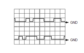
Reference: Inspection using an oscilloscope.
HINT:
- The correct waveform is as shown.
- VV1 stands for the camshaft position sensor signal (for intake camshaft), and EV1 stands for the camshaft position sensor signal (for exhaust camshaft).
ECM Terminal Name
CH1: Between VV1+ and VV1-
CH2: Between EV1+ and EV1-
Tester Range
5 V/DIV., 20 ms./DIV.
Condition
Idling with warm engine
MONITOR DESCRIPTION
If the output voltage transmitted by the camshaft position sensor (for exhaust camshaft) remains low or high, the ECM interprets this as a malfunction in the sensor circuit, illuminates the MIL and stores a DTC.
MONITOR STRATEGY
| Required Sensors/Components (Main) | Camshaft position sensor (for exhaust camshaft) |
| Required Sensors/Components (Related) | Crankshaft position sensor |
| Frequency of Operation | Continuous |
CONFIRMATION DRIVING PATTERN
- Connect the GTS to the DLC3.
- Turn the ignition switch to ON.
- Turn the GTS on.
- Clear the DTCs (even if no DTCs are stored, perform the clear DTC procedure).
- Turn the ignition switch off and wait for at least 30 seconds.
- Turn the ignition switch to ON.
- Turn the GTS on.
- Start the engine.
- Idle the engine for 10 seconds or more.
- Enter the following menus: Powertrain / Engine / Trouble Codes.
-
Read the pending DTCs.
HINT:
- If a pending DTC is output, the system is malfunctioning.
- If a pending DTC is not output, perform the following procedure.
- Enter the following menus: Powertrain / Engine / Utility / All Readiness.
- Input the DTC: P036511 or P036515.
-
Check the DTC judgment result.
GTS Display
Description
NORMAL
- DTC judgment completed
- System normal
ABNORMAL
- DTC judgment completed
- System abnormal
INCOMPLETE
- DTC judgment not completed
- Perform driving pattern after confirming DTC enabling conditions
HINT:
- If the judgment result is NORMAL, the system is normal.
- If the judgment result is ABNORMAL, the system is malfunctioning.
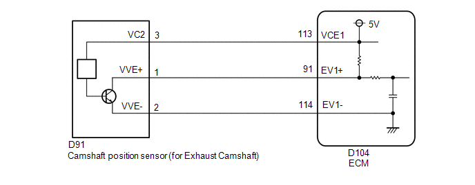
WIRING DIAGRAM
CAUTION / NOTICE / HINT
HINT:
Read Freeze Frame Data using the GTS. The ECM records vehicle and driving condition information as Freeze Frame Data the moment a DTC is stored. When troubleshooting, Freeze Frame Data can help determine if the vehicle was moving or stationary, if the engine was warmed up or not, if the air fuel ratio was lean or rich, and other data from the time the malfunction occurred.
PROCEDURE
| 1. | CHECK HARNESS AND CONNECTOR |
HINT:
Make sure that the connector is properly connected. If it is not, securely connect it and check for DTCs again.
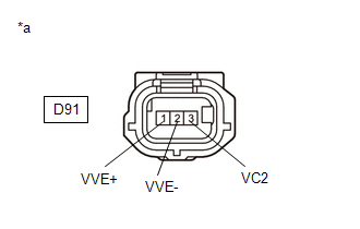
(a) Disconnect the camshaft position sensor (for exhaust camshaft) connector.
(b) Turn the ignition switch to ON.
| (c) Measure the voltage according to the value(s) in the table below. Standard Voltage:
|
|
(d) Turn the ignition switch off and wait for at least 30 seconds.
(e) Measure the resistance according to the value(s) in the table below.
Standard Resistance:
| Tester Connection | Condition | Specified Condition |
|---|---|---|
| D91-3(VC2) - D91-1(VVE+) | Ignition switch off | 1.425 to 1.575 kΩ |
| D91-2(VVE-) - Body ground | Always | Below 1 Ω |
| OK |
 | REPLACE CAMSHAFT POSITION SENSOR (FOR EXHAUST CAMSHAFT) |
|

| 2. | CHECK HARNESS AND CONNECTOR (CAMSHAFT POSITION SENSOR (FOR EXHAUST CAMSHAFT) - ECM) |
(a) Disconnect the camshaft position sensor (for exhaust camshaft) connector.
(b) Disconnect the ECM connector.
(c) Measure the resistance according to the value(s) in the table below.
Standard Resistance:
| Tester Connection | Condition | Specified Condition |
|---|---|---|
| D91-1(VVE+) - D104-91(EV1+) | Always | Below 1 Ω |
| D91-2(VVE-) - D104-114(EV1-) | Always | Below 1 Ω |
| D91-3(VC2) - D104-113(VCE1) | Always | Below 1 Ω |
| D91-1(VVE+) or D104-91(EV1+) - Body ground and other terminals | Always | 10 kΩ or higher |
| D91-2(VVE-) or D104-114(EV1-) - Body ground and other terminals | Always | 10 kΩ or higher |
| D91-3(VC2) or D104-113(VCE1) - Body ground and other terminals | Always | 10 kΩ or higher |
| OK |
 | REPLACE ECM |
| NG |
 | REPAIR OR REPLACE HARNESS OR CONNECTOR |
 Camshaft Position Sensor "B" Bank 1 No Signal (sub) (P036500)
DESCRIPTION Refer to DTC P036511. Click here
DTC No. Detection Item DTC Detection Condition Trouble Area MIL Note P036500 Camshaft Position Sensor "B" Bank 1 No Signal (sub) No camshaft position sensor (for exhaust camshaft) signal to the sub ECM while engine running ECM Comes on SAE: P0365 MONITOR DESCRIPTION While the engine is running, when the EV1 (EV2) signal is not input to the sub CPU even though the EV1 (EV2) signal is input to the main CPU, the ECM judges that a malfunction has occurred in an internal ECM circuit, and illuminates the MIL and stores a DTC...
 Camshaft Position Sensor "B" Bank 1 Signal Stuck in Range (P03652A,P036531)
DESCRIPTION Refer to DTC P036511. Click here
DTC No. Detection Item DTC Detection Condition Trouble Area MIL Note P03652A Camshaft Position Sensor "B" Bank 1 Signal Stuck in Range No camshaft position sensor (for exhaust camshaft) signal to ECM while engine cranking (1 trip detection logic)...
Other information:
Toyota Yaris XP210 (2020-2025) Reapir and Service Manual: Components
COMPONENTS ILLUSTRATION *1 COWL SIDE TRIM BOARD RH *2 FRONT DOOR SCUFF PLATE RH *3 FRONT DOOR OPENING TRIM WEATHERSTRIP RH *4 GLOVE COMPARTMENT DOOR ASSEMBLY *5 LOWER NO. 2 INSTRUMENT PANEL FINISH PANEL *6 CENTER LOWER INSTRUMENT COVER *7 LOWER INSTRUMENT PANEL FINISH PANEL *8 NO...
Toyota Yaris XP210 (2020-2025) Reapir and Service Manual: Diagnostic Trouble Code Chart
D..
Categories
- Manuals Home
- Toyota Yaris Owners Manual
- Toyota Yaris Service Manual
- Fuel Gauge
- G16e-gts (engine Mechanical)
- Immobilizer System
- New on site
- Most important about car
Refueling
Before refueling, close all the doors, windows, and the liftgate/trunk lid, and switch the ignition OFF.
To open the fuel-filler lid, pull the remote fuel-filler lid release.
