Toyota Yaris: Brake Actuator / Installation
INSTALLATION
CAUTION / NOTICE / HINT
NOTICE:
After performing the update ECU security key procedure, make sure to perform the initialization procedure for when the cable has been disconnected and reconnected to the negative (-) auxiliary battery terminal.
PROCEDURE
1. INSTALL BRAKE ACTUATOR BRACKET CUSHION
(a) Install the 3 brake actuator bracket cushions to the brake actuator bracket assembly.
2. INSTALL NO. 1 BRAKE ACTUATOR CASE COLLAR
(a) Install the 3 No. 1 brake actuator case collars to the brake actuator bracket cushion.
NOTICE:
Make sure that the No. 1 brake actuator case collar is in full contact with the brake actuator bracket cushion.
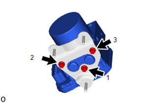
3. INSTALL BRAKE ACTUATOR ASSEMBLY
(a) Temporarily install the brake actuator assembly with the 3 bolts.
| (b) Fully tighten the 3 bolts in the order shown in the illustration. Torque: 5.4 N·m {55 kgf·cm, 48 in·lbf} NOTICE:
|
|
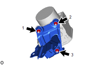
4. INSTALL NO. 1 BRAKE ACTUATOR BRACKET
(a) Temporarily install the No. 1 brake actuator bracket with the 3 bolts.
| (b) Fully tighten the 3 bolts in the order shown in the illustration. Torque: 5.4 N·m {55 kgf·cm, 48 in·lbf} NOTICE:
|
|
5. INSTALL BRAKE ACTUATOR WITH BRACKET
| (a) Temporarily install the brake actuator with bracket to the vehicle body with the bolt and 2 nuts. NOTICE:
HINT: Install the brake actuator with bracket while avoiding the brake lines. |
|
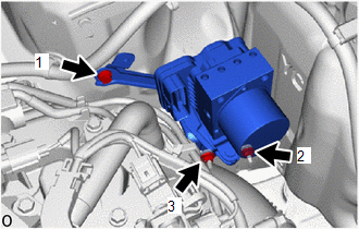
(b) Fully tighten the bolt and 2 nuts in the order shown in the illustration.
Torque:
19 N·m {194 kgf·cm, 14 ft·lbf}
| (c) Engage the clamp and install a new No. 2 brake tube clamp to the vehicle body. |
|
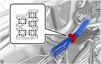
| (d) Engage the 5 clamps to install the No. 2 brake tube clamp to the brake lines. |
|
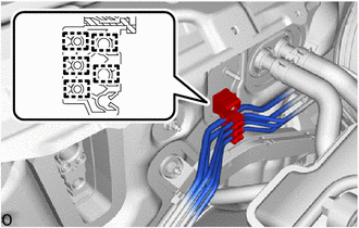
| (e) Engage the 5 clamps to install a new No. 1 brake tube clamp to the brake lines. |
|
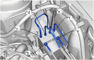
| (f) Temporarily tighten each brake line to the correct position on the brake actuator assembly as shown in the illustration. NOTICE:
|
|
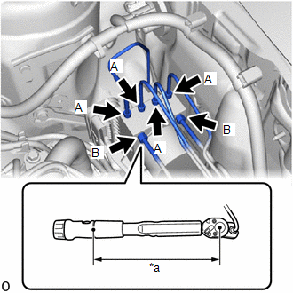
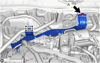
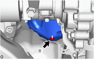
| (g) Using a union nut wrench, connect the 6 brake lines to the brake actuator assembly. Torque: Specified tightening torque (A) : 15.2 N·m {155 kgf·cm, 11 ft·lbf} Specified tightening torque (B) : 19.5 N·m {199 kgf·cm, 14 ft·lbf} NOTICE:
HINT:
|
|

(h) Connect the connector to the brake actuator assembly and lock the lock lever.
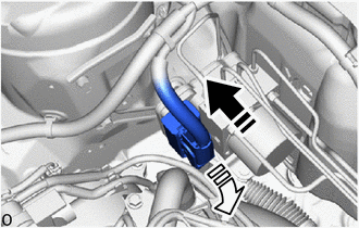
 | Connect the connector |
 | Lock the lock lever |
NOTICE:
- Make sure that the connector is locked securely.
- Make sure that the actuator connector can be connected smoothly.
- Do not allow water, oil or dirt to enter the connector.
(i) Return the air conditioning tube and accessory assembly to its original position.
NOTICE:
Do not apply excessive force to the return the air conditioning tube and accessory assembly to its original position..
6. INSTALL AIR CONDITIONING TUBE AND ACCESSORY ASSEMBLY
(a) Remove the vinyl tape from the air conditioning tube and accessory assembly.
(b) Sufficiently apply compressor oil to 2 new O-rings and the fitting surface of the air conditioning tube and accessory assembly.
Compressor Oil:
HFC-134a (R134a)
ND-OIL 8 or equivalent
(c) Install the 2 O-rings to the air conditioning tube and accessory assembly.
NOTICE:
Keep the O-ring and O-ring fitting surfaces free of foreign matter.
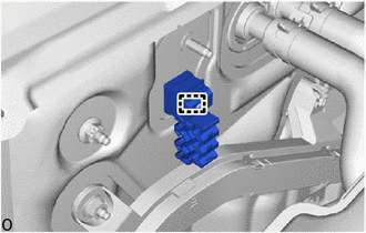
(d) Connect the air conditioning tube and accessory assembly to the air conditioning unit assembly.
| (e) Rotate the hook connector as shown in the illustration. |
|

(f) Insert the hose joint into the fitting hole securely and install the bolt.
Torque:
9.5 N·m {97 kgf·cm, 84 in·lbf}
(g) Engage the 2 clamps to install the air conditioning tube and accessory assembly.
7. INSTALL RESERVE SEALED TANK
(a) Install the reserve sealed tank with the 2 bolts.
Torque:
4.0 N·m {41 kgf·cm, 35 in·lbf}
8. INSTALL DASH PANEL HEAT INSULATOR
(a) Temporarily install the dash panel heat insulator to the vehicle body with the nut (A) and clamp.
| (1) Install the nut (B). Torque: 5.0 N·m {51 kgf·cm, 44 in·lbf} |
|
(2) Tighten the nut (A).
Torque:
5.0 N·m {51 kgf·cm, 44 in·lbf}
9. INSTALL NO. 1 ENGINE UNDER COVER ASSEMBLY
Click here

10. REMOVE NO. 1 ENGINE COVER SUB-ASSEMBLY
Click here

11. INSTALL OUTER COWL TOP PANEL SUB-ASSEMBLY
Click here

12. INSTALL WATER GUARD PLATE RH
Click here

13. INSTALL FRONT NO. 1 VENTILATOR SEAL
Click here

14. INSTALL WINDSHIELD WIPER MOTOR AND LINK ASSEMBLY
Click here

15. CONNECT CABLE TO NEGATIVE AUXILIARY BATTERY TERMINAL
Click here

16. UPDATE ECU SECURITY KEY
Click here

17. BLEED BRAKE SYSTEM
Click here

18. PERFORM INITIALIZATION AND CALIBRATION
Click here

19. PERFORM TEST MODE INSPECTION
Click here

20. INSPECT BRAKE ACTUATOR USING GTS
Click here

21. CHECK FOR CLEAR DTCS
Click here

22. CHARGE AIR CONDITIONING SYSTEM WITH REFRIGERANT
Click here

23. WARM UP ENGINE
Click here

24. INSPECT FOR REFRIGERANT LEAK
Click here

25. INITIALIZATION AFTER RECONNECTING AUXILIARY BATTERY TERMINAL
HINT:
When disconnecting and reconnecting the auxiliary battery, there is an automatic learning function that completes learning when the respective system is used.
Click here

 Removal
REMOVAL CAUTION / NOTICE / HINT The necessary procedures (adjustment, calibration, initialization, or registration) that must be performed after parts are removed, installed, or replaced during the brake actuator assembly removal/installation are shown below...

Other information:
Toyota Yaris XP210 (2020-2026) Owner's Manual: Temporary Spare Tire
Inspect the temporary spare tire at least monthly to make sure it is properly inflated and stored. The temporary spare tire is easier to handle because of its construction which is lighter and smaller than a conventional tire. This tire should be used only for an emergency and only for a short distance...
Toyota Yaris XP210 (2020-2026) Reapir and Service Manual: Problem Symptoms Table
PROBLEM SYMPTOMS TABLE NOTICE: When replacing the forward recognition camera, always replace it with a new one. If a forward recognition camera which was installed to another vehicle is used, the information stored in the forward recognition camera will not match the information from the vehicle and a DTC may be stored...
Categories
- Manuals Home
- Toyota Yaris Owners Manual
- Toyota Yaris Service Manual
- Brake System Control Module "A" System Voltage System Voltage Low (C137BA2)
- Diagnostic Trouble Code Chart
- How to connect USB port/Auxiliary jack
- New on site
- Most important about car
Liftgate/Trunk Lid
WARNING
Never allow a person to ride in the luggage compartment/trunk
Allowing a person to ride in the luggage compartment/trunk is dangerous. The person in the luggage compartment/trunk could be seriously injured or killed during sudden braking or a collision.
Do not drive with the liftgate/trunk lid open