Toyota Yaris: Brake Actuator / Removal
REMOVAL
CAUTION / NOTICE / HINT
The necessary procedures (adjustment, calibration, initialization, or registration) that must be performed after parts are removed, installed, or replaced during the brake actuator assembly removal/installation are shown below.
Necessary Procedure After Parts Removed/Installed/Replaced| Replacement Part or Procedure | Necessary Procedure | Effect/Inoperative when not Performed | Link |
|---|---|---|---|
| Skid control ECU (brake actuator assembly) | Update ECU security key | Vehicle control history (RoB) are stored |
|
| Calibration |
|
|


HINT:
When the cable is disconnected / reconnected to the auxiliary battery terminal, systems temporarily stop operating. However, each system has a function that completes learning the first time the system is used.
-
Learning completes when vehicle is driven
Effect/Inoperative Function When Necessary Procedures are not Performed
Necessary Procedures
Link
Lane tracing assist system
Drive the vehicle straight ahead at 35 km/h (22 mph) or more for 5 second or more.

Pre-collision system
Stop and start system
Drive the vehicle until stop and start control is permitted (approximately 5 to 60 minutes)

-
Learning completes when vehicle is operated normally
Effect/Inoperative Function When Necessary Procedures are not Performed
Necessary Procedures
Link
Power door lock control system
- Back door opener
Perform door unlock operation with door control switch or electrical key transmitter sub-assembly switch.

Air conditioning system
After the ignition switch is turned to ON, the servo motor standard position is recognized.
-
PROCEDURE
1. PRECAUTION
NOTICE:
After turning the ignition switch off, waiting time may be required before disconnecting the cable from the negative (-) battery terminal.
Click here

2. RECOVER REFRIGERANT FROM REFRIGERATION SYSTEM
Click here

3. DISCONNECT CABLE FROM NEGATIVE BATTERY TERMINAL
Click here

4. DRAIN BRAKE FLUID
NOTICE:
If brake fluid leaks onto any painted surface, immediately wash it off.
5. REMOVE WINDSHIELD WIPER MOTOR AND LINK ASSEMBLY
Click here

6. REMOVE FRONT NO. 1 VENTILATOR SEAL
Click here

7. REMOVE WATER GUARD PLATE RH
Click here

8. REMOVE OUTER COWL TOP PANEL SUB-ASSEMBLY
Click here

9. REMOVE NO. 1 ENGINE COVER SUB-ASSEMBLY
Click here

10. REMOVE NO. 1 ENGINE UNDER COVER ASSEMBLY
Click here

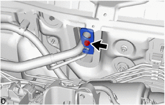
11. REMOVE DASH PANEL HEAT INSULATOR
| (a) Remove the nut. |
|
| (b) Remove the nut, clamp and dash panel heat insulator. |
|
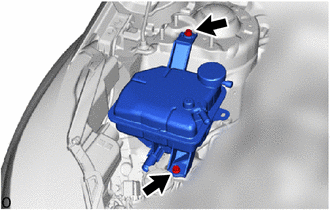
12. SEPARATE RESERVE SEALED TANK
| (a) Remove the 2 bolts to separate the reserve sealed tank. |
|
13. REMOVE AIR CONDITIONING TUBE AND ACCESSORY ASSEMBLY
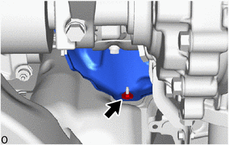
| (a) Remove the bolt. |
|
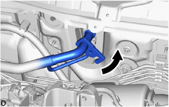
| (b) Rotate the hook connector and disconnect the air conditioning tube and accessory assembly as shown in the illustration. |
|
(c) Remove the 2 O-rings from the air conditioning tube and accessory assembly.
NOTICE:
Seal the openings of the disconnected parts using vinyl tape to prevent entry of moisture and foreign matter.
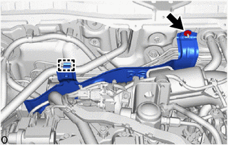
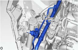
| (d) Disengage the 2 clamps to separate the air conditioning tube and accessory assembly. |
|
14. REMOVE BRAKE ACTUATOR WITH BRACKET
(a) Move aside the air conditioning tube and accessory assembly as shown in the illustration.
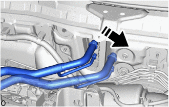
 | Move in this Direction |
NOTICE:
Do not apply excessive force to the air conditioning tube and accessory assembly.
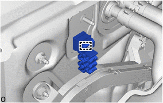
(b) Release the lock lever and disconnect the connector from the brake actuator assembly.
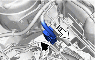
 | Release the lock lever |
 | Disconnect the connector |
NOTICE:
Be careful not to allow any brake fluid to enter the connector.
| (c) Use tags or make a memo to identify the places to reconnect the brake lines. |
|
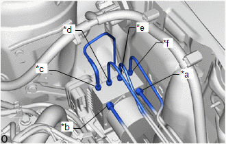
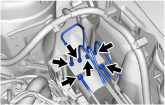
| (d) Using a union nut wrench, disconnect the 6 brake lines from the brake actuator assembly. NOTICE:
|
|
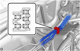
| (e) Disengage the 5 clamps to remove the No. 1 brake tube clamp from the brake lines. NOTICE: Do not kink or damage the brake lines. |
|
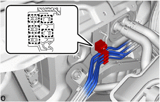
| (f) Disengage the 5 clamps to remove the No. 2 brake tube clamp from the brake lines. |
|
| (g) Disengage the clamp and remove the No. 2 brake tube clamp from the vehicle body. |
|
| (h) Remove the 2 nuts. |
|
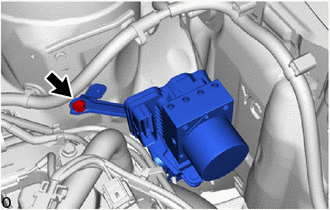
| (i) Remove the bolt and brake actuator with bracket. NOTICE:
HINT: Remove the brake actuator with bracket while avoiding the brake lines. |
|
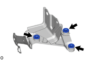
15. REMOVE NO. 1 BRAKE ACTUATOR BRACKET
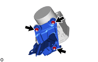
| (a) Remove the 3 nuts and No. 1 brake actuator bracket from the brake actuator bracket assembly. NOTICE:
|
|
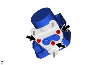
16. REMOVE BRAKE ACTUATOR ASSEMBLY
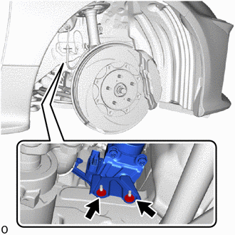
| (a) Remove the 3 bolts and brake actuator assembly from the brake actuator bracket assembly. NOTICE:
|
|
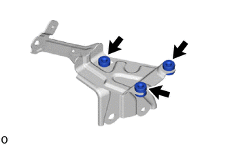
17. REMOVE NO. 1 BRAKE ACTUATOR CASE COLLAR
| (a) Remove the 3 No. 1 brake actuator case collars from the brake actuator bracket cushion. |
|
18. REMOVE BRAKE ACTUATOR BRACKET CUSHION
| (a) Remove the 3 brake actuator bracket cushions from the brake actuator bracket assembly. |
|
 On-vehicle Inspection
ON-VEHICLE INSPECTION PROCEDURE 1. CONNECT GTS (a) Connect the GTS to the DLC3 with the engine switch off. (b) Start the engine and run it at idle. (c) Turn the GTS on...
 Installation
INSTALLATION CAUTION / NOTICE / HINT NOTICE: After performing the update ECU security key procedure, make sure to perform the initialization procedure for when the cable has been disconnected and reconnected to the negative (-) auxiliary battery terminal...
Other information:
Toyota Yaris XP210 (2020-2026) Reapir and Service Manual: Fuel Rail Pressure Sensor (Low) Circuit Short to Battery or Open (P107A15)
DESCRIPTION Refer to DTC P107A11. Click here DTC No. Detection Item DTC Detection Condition Trouble Area MIL Note P107A15 Fuel Rail Pressure Sensor (Low) Circuit Short to Battery or Open The No. 2 fuel pressure sensor (for low pressure side) output voltage is higher than 4...
Toyota Yaris XP210 (2020-2026) Reapir and Service Manual: Room Temperature Sensor Circuit Short to Ground (B141A11)
DESCRIPTION The cooler thermistor (room temperature sensor) is installed in the instrument panel to detect the cabin temperature, which is used to control the air conditioning system. The resistance of the cooler thermistor (room temperature sensor) changes in accordance with the cabin temperature...
Categories
- Manuals Home
- Toyota Yaris Owners Manual
- Toyota Yaris Service Manual
- Fuse Panel Description
- G16e-gts (engine Mechanical)
- Key Battery Replacement
- New on site
- Most important about car
Keys

To use the auxiliary key, press the knob and pull out the auxiliary key from the smart key.
