Toyota Yaris: Fuel Pump (for High Pressure) / Installation
INSTALLATION
CAUTION / NOTICE / HINT
NOTICE:
This procedure includes the installation of small-head bolts. Refer to Small-Head Bolts of Basic Repair Hint to identify the small-head bolts.
Click here

PROCEDURE
1. TEMPORARILY INSTALL FUEL PUMP ASSEMBLY
NOTICE:
When replacing the fuel pump assembly, it is necessary to replace the No. 1 fuel pipe sub-assembly with a new one.
HINT:
Perform "Inspection After Repair" after replacing the fuel pump assembly.
Click here

| (a) Turn the crankshaft pulley until the flat of the No. 2 camshaft faces the fuel pump lifter assembly. HINT: This prevents the No. 2 camshaft nose from pushing up the fuel pump lifter assembly when installing the fuel pump assembly. |
|
| (b) Apply 30 cc (1.8 cu. in.) of engine oil to the pump drive cam. |
|
(c) Apply engine oil to the fuel pump lifter assembly.
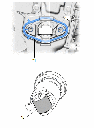
(d) Install a new fuel pump spacer gasket to the cylinder head cover sub-assembly.
| (e) Apply engine oil to the inside of the fuel pump lifter guide and the outside of the fuel pump lifter assembly. |
|
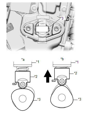
(f) Set the fuel pump lifter assembly on the fuel pump lifter guide as shown in the illustration.
HINT:
Align the stopper key of the fuel pump lifter assembly with the key groove of the fuel pump lifter guide.
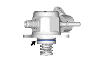
| (g) Apply engine oil to a new O-ring and install it to the fuel pump assembly. NOTICE: Do not damage the O-ring. |
|
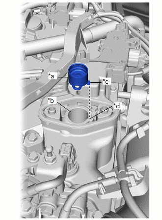
| (h) Set the fuel pump flange and fuel pump assembly on the cylinder head cover sub-assembly as shown in the illustration. |
|
(i) Temporarily install the fuel pump assembly with the 2 bolts, leaving some allowance for left and right movement.
2. INSTALL INTAKE AIR RESONATOR
(a) Install the intake air resonator to the fuel pump flange with the bolt.
3. INSTALL NO. 1 VACUUM TRANSMITTING HOSE
(a) Engage the 2 clamps and connect the No. 1 vacuum transmitting hose.
4. CONNECT ENGINE WIRE
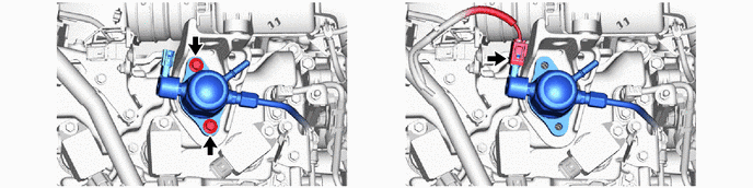
(a) Engage the clamp and connect the engine wire.
(b) Install the bolt.
Torque:
10 N·m {102 kgf·cm, 7 ft·lbf}
(c) Connect the 2 connectors.
5. TEMPORARILY INSTALL NO. 1 FUEL PIPE SUB-ASSEMBLY
NOTICE:
Do not damage the seals of the union nuts of the No. 1 fuel pipe sub-assembly.
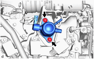
| (a) Temporarily install the bolt. |
|
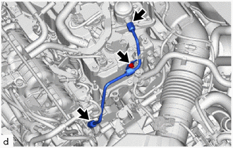
(b) Temporarily install the No. 1 fuel pipe sub-assembly to the fuel delivery pipe and tighten the union nut by hand.
(c) Temporarily install the No. 1 fuel pipe sub-assembly to the fuel pump assembly and tighten the union nut by hand.
6. INSTALL FUEL PUMP ASSEMBLY
(a) Tighten the 2 bolts.
Torque:
29 N·m {296 kgf·cm, 21 ft·lbf}
(b) Connect the fuel pump assembly connector.
7. INSTALL NO. 1 FUEL PIPE SUB-ASSEMBLY
(a) Using a 17 mm union nut wrench, tighten the union nut on the fuel delivery pipe side of the No. 1 fuel pipe sub-assembly.
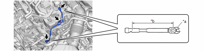
| *a | 17 mm Union Nut Wrench | *b | Torque Wrench Fulcrum Length |
Torque:
Specified tightening torque :
35 N·m {357 kgf·cm, 26 ft·lbf}
NOTICE:
Do not adjust the torque in the loosening direction.
HINT:
-
Calculate the torque wrench reading when changing the fulcrum length of the torque wrench.
Click here

- When using a 17 mm union nut wrench (fulcrum length of 30 mm (1.18 in.)) + torque wrench (fulcrum length of 180 mm (7.09 in.)): 30 N*m (306 kgf*cm, 22 ft.*lbf)
(b) Using a 17 mm union nut wrench, tighten the union nut on the fuel pump assembly side of the No. 1 fuel pipe sub-assembly.
Torque:
Specified tightening torque :
35 N·m {357 kgf·cm, 26 ft·lbf}
NOTICE:
Do not adjust the torque in the loosening direction.
HINT:
-
Calculate the torque wrench reading when changing the fulcrum length of the torque wrench.
Click here

- When using a 17 mm union nut wrench (fulcrum length of 30 mm (1.18 in.)) + torque wrench (fulcrum length of 180 mm (7.09 in.)): 30 N*m (306 kgf*cm, 22 ft.*lbf)
(c) Tighten the bolt.
Torque:
10 N·m {102 kgf·cm, 7 ft·lbf}
8. CONNECT NO. 1 WATER BY-PASS HOSE
(a) Connect the No. 1 water by-pass hose and slide the clip to secure it.
9. CONNECT NO. 8 WATER BY-PASS HOSE
(a) Connect the No. 8 water by-pass hose and slide the clip to secure it.
10. INSTALL NO. 2 FUEL TUBE SUB-ASSEMBLY
(a) Connect the No. 2 fuel tube sub-assembly to the fuel pump assembly and fuel delivery pipe.
(b) Install the No. 2 fuel tube sub-assembly with the bolt.
Torque:
10 N·m {102 kgf·cm, 7 ft·lbf}
11. INSTALL FUEL HOSE CLAMP
(a) Install the fuel pipe clamp to the No. 2 fuel tube sub-assembly.
12. CONNECT NO. 1 FUEL TUBE SUB-ASSEMBLY
(a) Connect the No. 1 fuel tube sub-assembly to the No. 2 fuel tube sub-assembly.
Click here

13. INSTALL NO. 1 VACUUM SWITCHING VALVE ASSEMBLY
Click here

14. INSTALL NO. 1 ENGINE COVER SUB-ASSEMBLY
Click here

15. INSTALL OUTER COWL TOP PANEL SUB-ASSEMBLY
Click here

16. INSTALL WATER GUARD PLATE RH
Click here

17. INSTALL FRONT NO. 1 VENTILATOR SEAL
Click here

18. INSTALL WINDSHIELD WIPER MOTOR AND LINK ASSEMBLY
Click here

19. CONNECT CABLE TO NEGATIVE AUXILIARY BATTERY TERMINAL
Click here

20. INITIALIZATION AFTER RECONNECTING AUXILIARY BATTERY TERMINAL
HINT:
When disconnecting and reconnecting the auxiliary battery, there is an automatic learning function that completes learning when the respective system is used.
Click here

21. INSPECT FOR FUEL LEAK
Click here

22. PERFORM INITIALIZATION
(a) Perform "Inspection After Repair" after replacing the fuel pump assembly.
Click here

 Inspection
INSPECTION PROCEDURE 1. INSPECT FUEL PUMP ASSEMBLY (a) Measure the resistance according to the value(s) in the table below. Standard Resistance: Tester Connection Condition Specified Condition D24-1 - D24-2 20°C (68°F) 0...
 Fuel Pump Ecu
ComponentsCOMPONENTS ILLUSTRATION
*1 FUEL PUMP CONTROL ECU BRACKET *2 FUEL PUMP CONTROL ECU *3 DECK TRIM SIDE PANEL ASSEMBLY RH - -
N*m (kgf*cm, ft...
Other information:
Toyota Yaris XP210 (2020-2026) Owner's Manual: Towing Description
We recommend that towing be done only by your Toyota dealer or a commercial tow-truck service. Proper lifting and towing are necessary to prevent damage to the vehicle. Government and local laws must be followed. A towed vehicle usually should have its drive wheels (front wheels) off the ground...
Toyota Yaris XP210 (2020-2026) Reapir and Service Manual: Brake Switch "B" Circuit Short to Battery (P070312)
DESCRIPTION The stop light switch assembly is part of a duplex system that transmits two signals: STP and ST1-. These two signals are used by the ECM to monitor whether or not the brake system is working properly. This DTC indicates that the stop light switch assembly remains on...
Categories
- Manuals Home
- Toyota Yaris Owners Manual
- Toyota Yaris Service Manual
- Diagnostic Trouble Code Chart
- How to use USB mode
- Key Battery Replacement
- New on site
- Most important about car
Keys

To use the auxiliary key, press the knob and pull out the auxiliary key from the smart key.
