Toyota Yaris: Wiper And Washer System / Wiper and Washer Switch Circuit
DESCRIPTION
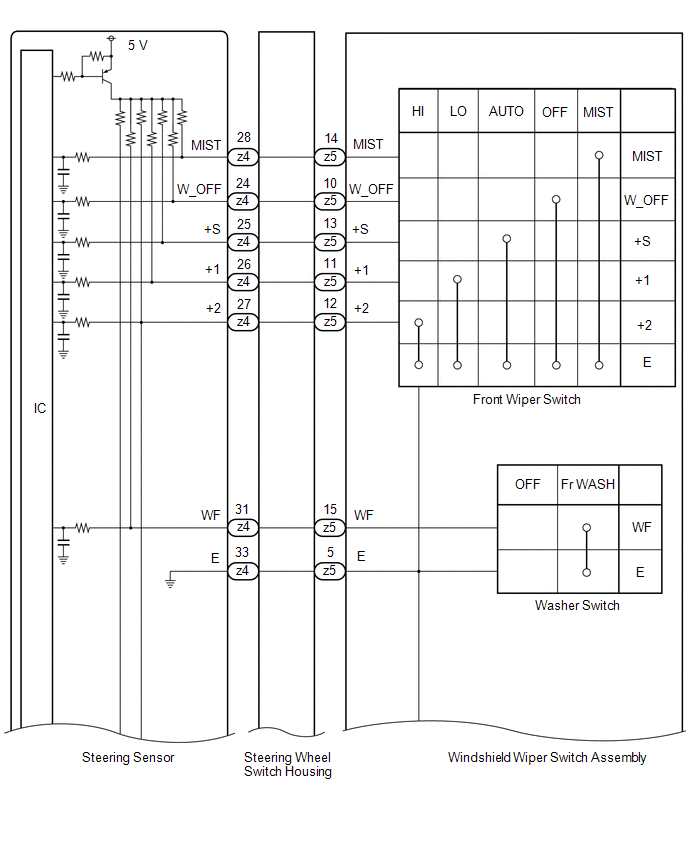
The condition of the windshield wiper switch assembly is detected and sent to the steering sensor in this circuit.
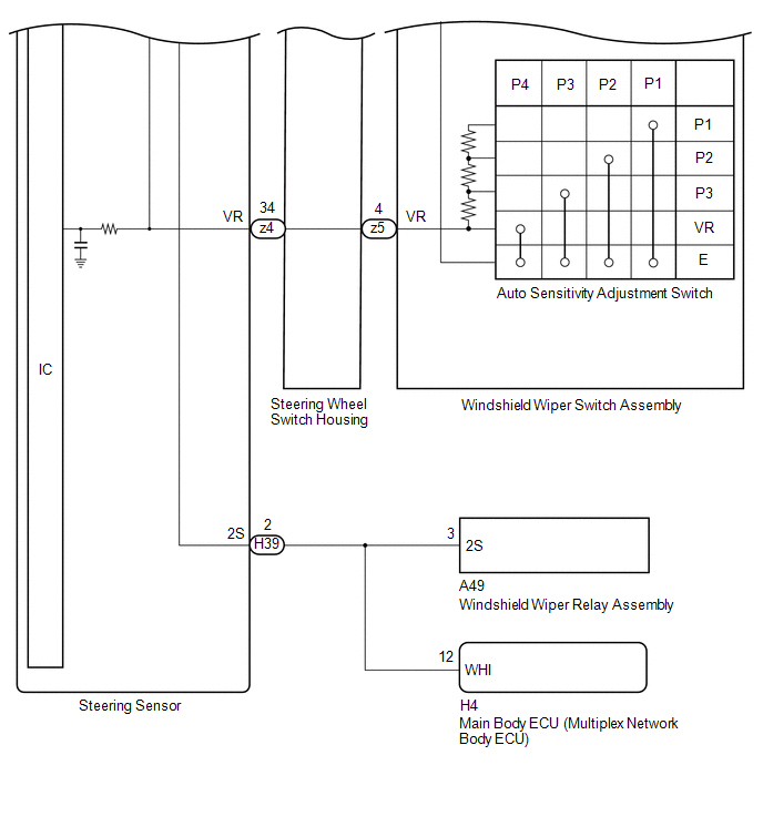
WIRING DIAGRAM
CAUTION / NOTICE / HINT
NOTICE:
If the main body ECU (multiplex network body ECU) is replaced, refer to the Registration.
Click here
.gif)
PROCEDURE
| 1. | READ VALUE USING GTS (STEERING ANGLE SENSOR) |
(a) Read the Data List according to the display on the GTS.
HINT:
Refer to Inspection for each position of the switch.
Click here
| Tester Display | Measurement Item | Range | Normal Condition | Diagnostic Note |
|---|---|---|---|---|
| Wiper OFF Switch | Front wiper switch OFF position signal | OFF or ON | OFF: Front wiper switch not in OFF position ON: Front wiper switch in OFF position | - |
| Wiper Auto/Int Switch | Front wiper switch INT position signal | OFF or ON | OFF: Front wiper switch not in INT position ON: Front wiper switch in INT position | - |
| Wiper Lo Switch | Front wiper switch LO position signal | OFF or ON | OFF: Front wiper switch not in LO position ON: Front wiper switch in LO position | - |
| Wiper Hi Switch | Front wiper switch HI position signal | OFF or ON | OFF: Front wiper switch not in HI position ON: Front wiper switch in HI position | - |
| Wiper Mist Switch | Front wiper switch MIST position signal | OFF or ON | OFF: Front wiper switch not in MIST position ON: Front wiper switch in MIST position | - |
| Washer Switch | Washer switch Fr WASH position signal | OFF or ON | OFF: Washer switch not in Fr WASH position ON: Washer switch in Fr WASH position | - |
| Tester Display |
|---|
| Wiper OFF Switch |
| Wiper Auto/Int Switch |
| Wiper Lo Switch |
| Wiper Hi Switch |
| Wiper Mist Switch |
| Washer Switch |
OK:
The GTS display changes correctly in response to the windshield wiper switch assembly operation.
| OK |
.gif) | PROCEED TO NEXT SUSPECTED AREA SHOWN IN PROBLEM SYMPTOMS TABLE |
|
.gif)
| 2. | INSPECT WINDSHIELD WIPER SWITCH ASSEMBLY |
Click here
| NG |
| REPLACE WINDSHIELD WIPER SWITCH ASSEMBLY |
|
| 3. | INSPECT STEERING WHEEL SWITCH HOUSING |
Click here
| NG |
| REPLACE STEERING WHEEL SWITCH HOUSING |
|
| 4. | CHECK HARNESS AND CONNECTOR (STEERING SENSOR - WINDSHIELD WIPER RELAY ASSEMBLY - MAIN BODY ECU (MULTIPLEX NETWORK BODY ECU)) |
(a) Disconnect the A49 windshield wiper relay Assembly connector.
(b) Disconnect the H4 main body ECU (multiplex network body ECU) connector.
(c) Measure the resistance according to the value(s) in the table below.
Standard Resistance:
| Tester Connection | Condition | Specified Condition |
|---|---|---|
| H39-2 (2S) - A49-3 (2S) | Always | Below 1 Ω |
| H39-2 (2S) or A49-3 (2S) - Body ground | Always | 10 kΩ or higher |
| H39-2 (2S) - H4-12 (WHI) | Always | Below 1 Ω |
| H39-2 (2S) or H4-12 (WHI) - Body ground | Always | 10 kΩ or higher |
| NG |
| REPAIR OR REPLACE HARNESS OR CONNECTOR |
|
| 5. | CHECK HARNESS AND CONNECTOR (WINDSHIELD WIPER RELAY ASSEMBLY) |
(a) Connect the A49 windshield wiper relay assembly connector.
(b) Measure the resistance according to the value(s) in the table below.
Standard Resistance:
| Tester Connection | Condition | Specified Condition |
|---|---|---|
| H39-2 (2S) - Body ground | Always | 10 kΩ or higher |
| NG |
| REPLACE WINDSHIELD WIPER RELAY ASSEMBLY |
|
| 6. | CHECK MAIN BODY ECU (MULTIPLEX NETWORK BODY ECU) |
(a) Disconnect the A49 windshield wiper relay assembly connector.
(b) Connect the H4 main body ECU (multiplex network body ECU) connector.
(c) Measure the resistance according to the value(s) in the table below.
Standard Resistance:
| Tester Connection | Condition | Specified Condition |
|---|---|---|
| H39-2 (2S) - Body ground | Always | 10 kΩ or higher |
| OK |
| REPLACE STEERING SENSOR |
| NG |
| REPLACE MAIN BODY ECU (MULTIPLEX NETWORK BODY ECU) |
 Front Wiper Motor Circuit
DESCRIPTION The windshield wiper relay assembly controls the windshield wiper motor assembly through this circuit. WIRING DIAGRAM
PROCEDURE 1. PERFORM ACTIVE TEST USING GTS (FRONT WIPER LO OPERATION / FRONT WIPER HI OPERATION) (a) Perform the Active Test according to the display on the GTS...
 Washer Motor Circuit
DESCRIPTION When the windshield washer motor and pump assembly receives signals from the windshield wiper switch assembly, it operates to spray washer fluid from the washer nozzle sub-assemblies...
Other information:
Toyota Yaris XP210 (2020-2026) Reapir and Service Manual: HO2S Heater Control Circuit Bank 1 Sensor 2 Circuit Short to Battery (P003612,P003613,P102A9E)
DESCRIPTION The air fuel ratio sensor (sensor 2) generates current that corresponds to the actual air fuel ratio. This sensor current is used to provide the ECM with feedback so that it can control the air fuel ratio. The ECM determines the deviation from the stoichiometric air fuel ratio level, and regulates the fuel injection duration...
Toyota Yaris XP210 (2020-2026) Reapir and Service Manual: How To Proceed With Troubleshooting
CAUTION / NOTICE / HINT HINT: Use these procedures to troubleshoot the power integration system. *: Use the GTS. PROCEDURE 1. VEHICLE BROUGHT TO WORKSHOP NEXT 2. INSPECT AUXILIARY BATTERY VOLTAGE (a) Measure the auxiliary battery voltage with the ignition switch off...
Categories
- Manuals Home
- Toyota Yaris Owners Manual
- Toyota Yaris Service Manual
- To Set Speed
- Engine Start Function When Key Battery is Dead
- How to use USB mode
- New on site
- Most important about car
Keys

To use the auxiliary key, press the knob and pull out the auxiliary key from the smart key.
