Toyota Yaris: Air Fuel Ratio Sensor (for Sensor 2) / Removal
REMOVAL
CAUTION / NOTICE / HINT
The necessary procedures (adjustment, calibration, initialization, or registration) that must be performed after parts are removed, installed, or replaced during the No. 2 air fuel ratio sensor removal/installation are shown below.
Necessary Procedure After Parts Removed/Installed/Replaced| Replacement Part or Procedure | Necessary Procedure | Effect/Inoperative when not Performed | Link |
|---|---|---|---|
| Inspection after repair |
|
|

CAUTION:
-
When the engine is hot, do not touch high-temperature areas such as the engine or exhaust pipe.
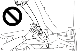
- Touching high-temperature areas such as the engine and exhaust pipe could result in burns.
PROCEDURE
1. REMOVE CENTER NO. 4 ENGINE UNDER COVER
Click here

2. REMOVE CENTER FRONT FLOOR BRACE
Click here

3. REMOVE CENTER NO. 1 FLOOR BRACE
Click here

4. REMOVE NO. 2 AIR FUEL RATIO SENSOR
| (a) Disconnect the No. 2 air fuel ratio sensor connector. |
|
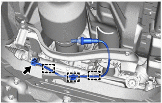
(b) Disengage the 3 wire harness clamps.
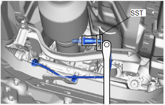
| (c) Using SST, remove the No. 2 air fuel ratio sensor from the front exhaust pipe assembly. SST: 09224-00012 NOTICE: If the No. 2 air fuel ratio sensor has been struck or dropped, replace it. |
|
 Components
COMPONENTS ILLUSTRATION
*1 NO. 2 AIR FUEL RATIO SENSOR *2 CENTER NO. 1 FLOOR BRACE *3 CENTER FRONT FLOOR BRACE *4 CENTER NO. 4 ENGINE UNDER COVER
N*m (kgf*cm, ft...
 Inspection
INSPECTION PROCEDURE 1. INSPECT NO. 2 AIR FUEL RATIO SENSOR (a) Measure the resistance according to the value(s) in the table below. Standard Resistance: Tester Connection Condition Specified Condition D109-1(HA1B) - D109-2(+B) 20°C (68°F) 1...
Other information:
Toyota Yaris XP210 (2020-2026) Reapir and Service Manual: Parts Location
PARTS LOCATION ILLUSTRATION *1 SEMICONDUCTOR POWER INTEGRATION ECU *2 NO. 1 ENGINE ROOM RELAY BLOCK - STD P/I NO. 1 FUSE - INP STD NO. 1-1 FUSE ILLUSTRATION *1 MAIN BODY ECU (MULTIPLEX NETWORK BODY ECU) *2 POWER DISTRIBUTION BOX ASSEMBLY - ECU-IGR NO...
Toyota Yaris XP210 (2020-2026) Reapir and Service Manual: Removal
REMOVAL CAUTION / NOTICE / HINT The necessary procedures (adjustment, calibration, initialization, or registration) that must be performed after parts are removed and installed, or replaced during rear suspension arm assembly removal/installation are shown below...
Categories
- Manuals Home
- Toyota Yaris Owners Manual
- Toyota Yaris Service Manual
- How to connect USB port/Auxiliary jack
- Battery Monitor Module General Electrical Failure (P058A01)
- Auto Lock/Unlock Function
- New on site
- Most important about car
Fuel Gauge
The fuel gauge shows approximately how much fuel is remaining in the tank when the ignition is switched ON. We recommend keeping the tank over 1/4 full.
