Toyota Yaris: Smart Key System (for Start Function) / Unable to Unlock Steering Wheel (Engine cannot Start)
DESCRIPTION
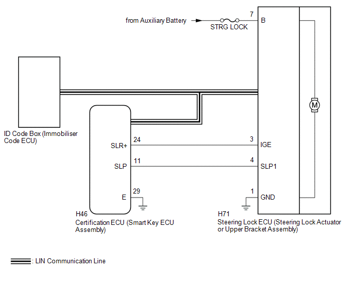
The steering lock ECU (steering lock actuator or upper bracket assembly) activates the steering lock motor and moves the lock bar into the steering column to lock the steering.
The steering may not unlock when the lock bar gets stuck in the lock hole of the steering column. In this case, if the ignition switch is turned to ON while shaking the steering wheel, as is done for a vehicle with a mechanical key, the lock bar will be unlocked. If the certification ECU (smart key ECU assembly), ID code box (immobiliser code ECU) or ECM is replaced, the system needs to be initialized. Otherwise, the steering cannot be unlocked and the engine cannot be started.
Related Data List and Active Test Items| Problem Symptom | Data List and Active Test |
|---|---|
| Unable to unlock steering wheel (Engine cannot start) | Smart Key
|
WIRING DIAGRAM
CAUTION / NOTICE / HINT
NOTICE:
- When using the GTS with the ignition switch off, connect the GTS to the DLC3 and turn a courtesy light switch on and off at intervals of 1.5 seconds or less until communication between the GTS and the vehicle begins. Then select the vehicle type under manual mode and enter the following menus: Body Electrical / Smart Key. While using the GTS, periodically turn a courtesy light switch on and off at intervals of 1.5 seconds or less to maintain communication between the GTS and the vehicle.
-
Perform either of the following operations to lock/unlock the steering:
- To unlock the steering, carry the electrical key transmitter sub-assembly and turn the ignition switch to ACC or ON.
- To lock the steering, turn the ignition switch off and then open a door.
-
The smart key system (for Start Function) uses the LIN communication system and CAN communication system. Inspect the communication function by following How to Proceed with Troubleshooting. Troubleshoot the smart key system (for Start Function) after confirming that the communication systems are functioning properly.
Click here

- After performing repairs, confirm that the problem does not recur.
- Make sure that no DTCs are output. If any DTCs are output, proceed to Diagnostic Trouble Code Chart.
- Inspect the fuses for circuits related to this system before performing the following procedure.
-
Before replacing the steering lock ECU (steering lock actuator or upper bracket assembly), ID code box (immobiliser code ECU) or certification ECU (smart key ECU assembly), refer to Registration.
Click here

- When disconnecting the cable from the negative (-) auxiliary battery terminal, some systems need to be initialized after the cable is reconnected.
- If the steering lock ECU (steering lock actuator or upper bracket assembly) is replaced, be sure to confirm that the steering is unlocked by turning the steering wheel to the left and right before starting the engine. This function prevents the engine from starting while the steering is locked. If the steering is locked for any reason, open and close a door with the ignition switch off, and then unlock the steering by pressing the engine switch.
- After repair, confirm that no DTCs are output by performing "DTC Output Confirmation Operation".
PROCEDURE
| 1. | CHECK ENGINE SWITCH (SWITCH CONDITION) |
(a) Check the power source mode change.
(1) When the electrical key transmitter sub-assembly is inside the vehicle, check that pressing the engine switch with the clutch pedal released causes the power source mode to change as follows:
OK:
Off → ACC → ON → Off
| NG |
 | GO TO OTHER PROBLEM |
|

| 2. | CHECK MULTI-INFORMATION DISPLAY |
(a) With the ignition switch ON, check that Steering Lock active is displayed on the multi-information display in the combination meter assembly.
| Result | Proceed to |
|---|---|
| Steering Lock active is displayed | A |
| Steering Lock active is not displayed | B |
| B |
 | GO TO STEP 4 |
|

| 3. | CHECK STEERING UNLOCK |
(a) Turn the steering wheel left and right, and then press the engine switch.
(b) Check that the steering is unlocked.
| Result | Proceed to |
|---|---|
| The steering is unlocked | A |
| The steering is not unlocked | B |
| A |
 | END (STEERING LOCK NORMAL) |
|

| 4. | CHECK FOR DTC |
(a) Check for DTCs.
Body Electrical > Smart Key > Trouble CodesNOTICE:
If a malfunction occurs, do not remove/install the vehicle auxiliary battery before checking for DTCs.
OK:
DTCs are not output.
| NG |
 | GO TO DIAGNOSTIC TROUBLE CODE CHART |
|

| 5. | READ VALUE USING GTS (STEERING UNLOCK REQUEST RECEIVE) |
(a) Read the Data List according to the display on the GTS.
Body Electrical > Smart Key > Data List| Tester Display | Measurement Item | Range | Normal Condition | Diagnostic Note |
|---|---|---|---|---|
| Steering Unlock Request Receive | Status of steering unlock command from certification ECU (smart key ECU assembly) | OK or NG | OK: Certification ECU (smart key ECU assembly) sends steering unlock command (within 10 seconds of ignition switch turned ACC or ON, or of engine start operation performed) NG: Certification ECU (smart key ECU assembly) does not send steering unlock command (ignition switch not turned ACC or ON, and engine start operation not performed) |
|
| Tester Display |
|---|
| Steering Unlock Request Receive |
OK:
Within 10 seconds of turning the ignition switch to ACC or ON or starting the engine, the Data List item changes to "OK".
| NG |
 | GO TO STEP 14 |
|

| 6. | READ VALUE USING GTS (S CODE CHECK) |
(a) Read the Data List according to the display on the GTS.
Body Electrical > Smart Key > Data List| Tester Display | Measurement Item | Range | Normal Condition | Diagnostic Note |
|---|---|---|---|---|
| S Code Check | Verification result between certification ECU (smart key ECU assembly) and ID code box (immobiliser code ECU) | OK or NG | OK: Verification result normal NG: Verification result abnormal | When NG is displayed:
|
| Tester Display |
|---|
| S Code Check |
OK:
OK is displayed on the GTS.
HINT:
Reasons for verification failure:
- The certification ECU (smart key ECU assembly) or ID code box (immobiliser code ECU) is malfunctioning.
- There is a problem with the communication between ECUs.
- An ECU was replaced, but not registered.
- An ECU was replaced with an ECU which has already been registered to another vehicle.
| NG |
 | GO TO STEP 13 |
|

| 7. | READ VALUE USING GTS (L CODE CHECK) |
(a) Read the Data List according to the display on the GTS.
Body Electrical > Smart Key > Data List| Tester Display | Measurement Item | Range | Normal Condition | Diagnostic Note |
|---|---|---|---|---|
| L Code Check | Verification result between ID code box (immobiliser code ECU) and steering lock ECU (steering lock actuator or upper bracket assembly) | OK or NG | OK: Verification result normal NG: Verification result abnormal | When NG is displayed:
|
| Tester Display |
|---|
| L Code Check |
OK:
OK is displayed on the GTS.
HINT:
Reasons for verification failure:
- The steering lock ECU (steering lock actuator or upper bracket assembly) or ID code box (immobiliser code ECU) is malfunctioning.
- There is a problem with the communication between ECUs.
- An ECU is replaced, but is not registered.
- An ECU is replaced with an ECU which has a code already stored in it.
| NG |
 | GO TO STEP 12 |
|

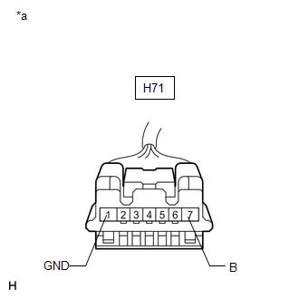
| 8. | CHECK HARNESS AND CONNECTOR (POWER SOURCE AND GROUND) |
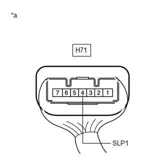
(a) Disconnect the H71 steering lock ECU (steering lock actuator or upper bracket assembly) connector.
| (b) Measure the resistance according to the value(s) in the table below. Standard Resistance:
NOTICE: If the result is not as specified, check for looseness in the ground cable connection. |
|
(c) Measure the voltage according to the value(s) in the table below.
Standard Voltage:
| Tester Connection | Condition | Specified Condition |
|---|---|---|
| H71-7 (B) - Body ground | Always | 11 to 14 V |
| NG |
 | REPAIR OR REPLACE HARNESS OR CONNECTOR |
|

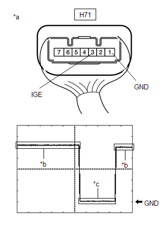
| 9. | CHECK STEERING LOCK ECU (STEERING LOCK ACTUATOR OR UPPER BRACKET ASSEMBLY) |
(a) Reconnect the H71 steering lock ECU (steering lock actuator or upper bracket assembly) connector.
| (b) Check the signal waveform according to the condition(s) in the table below. Measurement Condition
|
|
| OK |
 | REPLACE STEERING LOCK ECU (STEERING LOCK ACTUATOR OR UPPER BRACKET ASSEMBLY) |
|

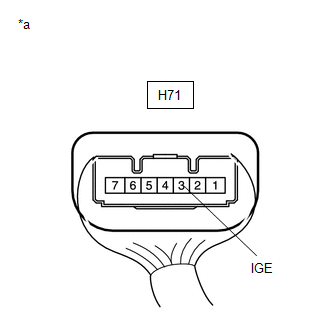
| 10. | CHECK HARNESS AND CONNECTOR (STEERING LOCK ECU (STEERING LOCK ACTUATOR OR UPPER BRACKET ASSEMBLY) - CERTIFICATION ECU (SMART KEY ECU ASSEMBLY)) |
(a) Disconnect the H71 steering lock ECU (steering lock actuator or upper bracket assembly) connector.
(b) Disconnect the H46 certification ECU (smart key ECU assembly) connector.
(c) Measure the resistance according to the value(s) in the table below.
Standard Resistance:
| Tester Connection | Condition | Specified Condition |
|---|---|---|
| H71-3 (IGE) - H46-24 (SLR+) | Always | Below 1 Ω |
| H71-3 (IGE) or H46-24 (SLR+) - Other terminals and body ground | Always | 10 kΩ or higher |
(d) Reconnect the H71 steering lock ECU (steering lock actuator or upper bracket assembly) connector.
(e) Reconnect the H46 certification ECU (smart key ECU assembly) connector.
| NG |
 | REPAIR OR REPLACE HARNESS OR CONNECTOR |
|

| 11. | CHECK STEERING LOCK ECU (STEERING LOCK ACTUATOR OR UPPER BRACKET ASSEMBLY) |
| (a) Measure the voltage according to the value(s) inthe table below. Standard Voltage:
|
|
| OK |
 | REPLACE CERTIFICATION ECU (SMART KEY ECU ASSEMBLY) |
| NG |
 | REPLACE STEERING LOCK ECU (STEERING LOCK ACTUATOR OR UPPER BRACKET ASSEMBLY) |
| 12. | CHECK STEERING LOCK ECU (STEERING LOCK ACTUATOR OR UPPER BRACKET ASSEMBLY) |
(a) Replace the steering lock ECU (steering lock actuator or upper bracket assembly) with a new one and perform registration.
HINT:
-
For replacement.
Click here

-
For registration.
Click here

(b) Read the Data List according to the display on the GTS.
Body Electrical > Smart Key > Data List| Tester Display | Measurement Item | Range | Normal Condition | Diagnostic Note |
|---|---|---|---|---|
| L Code Check | Verification result between ID code box (immobiliser code ECU) and steering lock ECU (steering lock actuator or upper bracket assembly) | OK or NG | OK: Verification result normal NG: Verification result abnormal | When NG is displayed:
|
| Tester Display |
|---|
| L Code Check |
OK:
OK is displayed on the GTS.
| OK |
 | END (STEERING LOCK ECU (STEERING LOCK ACTUATOR OR UPPER BRACKET ASSEMBLY) WAS DEFECTIVE) |
| NG |
 | REPLACE CERTIFICATION ECU (SMART KEY ECU ASSEMBLY) |
| 13. | CHECK CERTIFICATION ECU (SMART KEY ECU ASSEMBLY) |
(a) Replace the certification ECU (smart key ECU assembly) with a new one and perform registration.
HINT:
-
For replacement.
Click here

-
For registration.
Click here

(b) Read the Data List according to the display on the GTS.
Body Electrical > Smart Key > Data List| Tester Display | Measurement Item | Range | Normal Condition | Diagnostic Note |
|---|---|---|---|---|
| S Code Check | Verification result between certification ECU (smart key ECU assembly) and ID code box (immobiliser code ECU) | OK or NG | OK: Verification result normal NG: Verification result abnormal | When NG is displayed:
|
| Tester Display |
|---|
| S Code Check |
OK:
OK is displayed on the GTS.
| OK |
 | END (CERTIFICATION ECU (SMART KEY ECU ASSEMBLY) WAS DEFECTIVE) |
| NG |
 | REPLACE ID CODE BOX (IMMOBILISER CODE ECU) |
| 14. | CHECK STEERING LOCK ECU (STEERING LOCK ACTUATOR OR UPPER BRACKET ASSEMBLY) |
| (a) Measure the voltage according to the value(s) in the table below. Standard Voltage:
|
|
| NG |
 | GO TO STEP 16 |
|

| 15. | READ VALUE USING GTS (STEERING UNLOCK REQUEST RECEIVE) |
(a) Replace the certification ECU (smart key ECU assembly) with a new one and perform registration.
HINT:
-
For replacement.
Click here

-
For registration.
Click here

(b) Turn the ignition switch to ON.
(c) Read the Data List according to the display on the GTS.
Body Electrical > Smart Key > Data List| Tester Display | Measurement Item | Range | Normal Condition | Diagnostic Note |
|---|---|---|---|---|
| Steering Unlock Request Receive | Status of steering unlock command from certification ECU (smart key ECU assembly) | OK or NG | OK: Certification ECU (smart key ECU assembly) sends steering unlock command (within 10 seconds of ignition switch turned ACC or ON, or of engine start operation performed) NG: Certification ECU (smart key ECU assembly) does not send steering unlock command (ignition switch not turned ACC or ON, and engine start operation not performed) |
|
| Tester Display |
|---|
| Steering Unlock Request Receive |
OK:
Within 10 seconds after the ignition switch is turned to ACC or ON or the engine is started, the Data List item changes to "OK".
| OK |
 | END (CERTIFICATION ECU (SMART KEY ECU ASSEMBLY) WAS DEFECTIVE) |
| NG |
 | REPLACE STEERING LOCK ECU (STEERING LOCK ACTUATOR OR UPPER BRACKET ASSEMBLY) |
| 16. | CHECK HARNESS AND CONNECTOR (STEERING LOCK ECU (STEERING LOCK ACTUATOR OR UPPER BRACKET ASSEMBLY) - CERTIFICATION ECU (SMART KEY ECU ASSEMBLY)) |
(a) Disconnect the H71 steering lock ECU (steering lock actuator or upper bracket assembly) connector.
(b) Disconnect the H46 certification ECU (smart key ECU assembly) connector.
(c) Measure the resistance according to the value(s) in the table below.
Standard Resistance:
| Tester Connection | Condition | Specified Condition |
|---|---|---|
| H71-4 (SLP1) - H46-11 (SLP) | Always | Below 1 Ω |
| H71-4 (SLP1) or H46-11 (SLP) - Other terminals and body ground | Always | 10 kΩ or higher |
| NG |
 | REPAIR OR REPLACE HARNESS OR CONNECTOR |
|

| 17. | READ VALUE USING GTS (STEERING UNLOCK REQUEST RECEIVE) |
(a) Replace the steering lock ECU (steering lock actuator or upper bracket assembly) with a new one.
Click here

(b) Perform registration.
(c) Turn the ignition switch to ON.
(d) Use the Data List to check if the steering lock request is functioning properly.
Body Electrical > Smart Key > Data List| Tester Display | Measurement Item | Range | Normal Condition | Diagnostic Note |
|---|---|---|---|---|
| Steering Unlock Request Receive | Status of steering unlock command from certification ECU (smart key ECU assembly) | OK or NG | OK: Certification ECU (smart key ECU assembly) sends steering unlock command (within 10 seconds of ignition switch turned ACC or ON, or of engine start operation performed) NG: Certification ECU (smart key ECU assembly) does not send steering unlock command (ignition switch not turned ACC or ON, and engine start operation not performed) |
|
| Tester Display |
|---|
| Steering Unlock Request Receive |
OK:
Within 10 seconds of turning the ignition switch to ACC or ON or starting the engine, the Data List item changes to "OK".
| OK |
 | END (STEERING LOCK ECU (STEERING LOCK ACTUATOR OR UPPER BRACKET ASSEMBLY) WAS) |
| NG |
 | REPLACE CERTIFICATION ECU (SMART KEY ECU ASSEMBLY) |
 Immobiliser System does not Operate Properly
DESCRIPTION The immobiliser function compares the ID code that is registered in the certification ECU (smart key ECU assembly) with the ID code of the transponder chip that is embedded in the electrical key transmitter sub-assembly...

Other information:
Toyota Yaris XP210 (2020-2026) Reapir and Service Manual: Headup Display
ComponentsCOMPONENTS ILLUSTRATION *1 METER MIRROR SUB-ASSEMBLY *2 NO. 1 HEATER TO REGISTER DUCT SUB-ASSEMBLY RemovalREMOVAL CAUTION / NOTICE / HINT HINT: When the cable is disconnected/reconnected to the auxiliary battery terminal, systems temporarily stop operating...
Toyota Yaris XP210 (2020-2026) Owner's Manual: How to connect USB port/Auxiliary jack
USB port Auxiliary jack Connecting a device Connect the connector on the device to the USB port. Connecting with a connector cable Connect the device plug/connector cable to the auxiliary jack/USB port. Insert the plug into the auxiliary jack/USB port securely...
Categories
- Manuals Home
- Toyota Yaris Owners Manual
- Toyota Yaris Service Manual
- Maintenance
- Headlights
- Brake System Control Module "A" System Voltage System Voltage Low (C137BA2)
- New on site
- Most important about car
Fuel Gauge
The fuel gauge shows approximately how much fuel is remaining in the tank when the ignition is switched ON. We recommend keeping the tank over 1/4 full.
