Toyota Yaris: Smart Key System (for Start Function) / Immobiliser System does not Operate Properly
DESCRIPTION
The immobiliser function compares the ID code that is registered in the certification ECU (smart key ECU assembly) with the ID code of the transponder chip that is embedded in the electrical key transmitter sub-assembly.
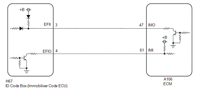
WIRING DIAGRAM
CAUTION / NOTICE / HINT
NOTICE:
- When using the GTS with the ignition switch off, connect the GTS to the DLC3 and turn a courtesy light switch on and off at intervals of 1.5 seconds or less until communication between the GTS and the vehicle begins. Then select the vehicle type under manual mode and enter the following menus: Body Electrical / Smart Key. While using the GTS, periodically turn a courtesy light switch on and off at intervals of 1.5 seconds or less to maintain communication between the GTS and the vehicle.
-
The smart key system (for Start Function) uses the LIN communication system and CAN communication system. Inspect the communication function by following How to Proceed with Troubleshooting. Troubleshoot the smart key system (for Start Function) after confirming that the communication systems are functioning properly.
Click here

-
Before replacing the ECM or ID code box (immobiliser code ECU), refer to Registration.
Click here

- After repair, confirm that no DTCs are output by performing "DTC Output Confirmation Operation".
HINT:
If an immobiliser function or engine DTC is output, first perform troubleshooting for the immobiliser function or engine DTC.
PROCEDURE
| 1. | CHECK FOR DTC |
(a) Check for DTCs.
Body Electrical > Smart Key > Trouble Codes Powertrain > Engine > Trouble Codes| Result | Proceed to |
|---|---|
| DTCs are not output | A |
| DTCs are output | B |
| B |
 | GO TO DIAGNOSTIC TROUBLE CODE CHART |
|

| 2. | READ VALUE USING GTS (IMMOBILISER FUEL CUT) |
(a) Read the Data List according to the display on the GTS.
Powertrain > Engine > Data List| Tester Display | Measurement Item | Range | Normal Condition | Diagnostic Note |
|---|---|---|---|---|
| Immobiliser Fuel Cut Status | Immobiliser fuel cut status | OFF or ON | OFF: Fuel cut OFF ON: Fuel cut ON | - |
| Tester Display |
|---|
| Immobiliser Fuel Cut Status |
| Result | Proceed to |
|---|---|
| On the GTS screen, ON is displayed. | A |
| On the GTS screen, OFF is displayed. | B |
| A |
 | GO TO SFI SYSTEM (HOW TO PROCEED WITH TROUBLESHOOTING) |
|

| 3. | CHECK WHETHER ENGINE STARTS |
(a) Check that the engine starts after 5 seconds of the ignition switch being turned to ON.
OK:
Engine starts normally.
| OK |
 | USE SIMULATION METHOD TO CHECK |
|

| 4. | CHECK ID CODE BOX (IMMOBILISER CODE ECU) (TERMINAL EFIO AND EFII) |
(a) Using an oscilloscope, check the waveform.
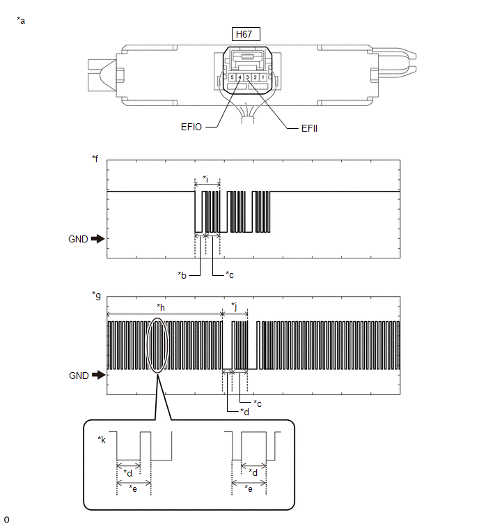
| *a | Component with harness connected (ID Code Box (Immobiliser Code ECU)) | *b | Approximately 160 ms. |
| *c | Approximately 270 ms. | *d | Approximately 40 ms. |
| *e | Approximately 60 ms. | *f | Waveform (EFII) |
| *g | Waveform (EFIO) | *h | Waveform 1 |
| *i | Waveform 2 | *j | Waveform 3 |
| *k | Waveform 1 (detail) | - | - |
NOTICE:
The waveform shown in the illustration is an example for reference only. Noise, chattering, etc. are not shown.
OK:
| Tester Connection | Condition | Tool Setting | Specified Condition |
|---|---|---|---|
| H67-3 (EFII) - Body ground | Within 3 seconds of engine start or within 3 seconds of ignition switch turned to ON after auxiliary battery cable disconnected and reconnected | 2 V/DIV., 500 ms./DIV. | Pulse generation (See waveform 2) |
| H67-4 (EFIO) - Body ground | Within 3 seconds of engine start or within 3 seconds of ignition switch turned to ON after auxiliary battery cable disconnected and reconnected | 2 V/DIV., 500 ms./DIV. | Pulse generation (See waveform 1 and 3) |
| Result | Proceed to |
|---|---|
| Normal waveform | A |
| Waveform 1 is not output, or has abnormal wavelength or shape | B |
| Waveform 2 is not output, or has abnormal wavelength or shape | C |
| Waveform 3 is not output, or has abnormal wavelength or shape | D |
| B |
 | GO TO STEP 7 |
| C |
 | REPLACE ECM |
| D |
 | GO TO STEP 8 |
|

| 5. | REGISTER ECU COMMUNICATION ID |
(a) Register the ECU communication ID codes.
Click here

|

| 6. | CHECK WHETHER ENGINE STARTS |
(a) Check that the engine starts.
OK:
Engine starts normally.
| OK |
 | END (COMMUNICATION ID REGISTRATION WAS DEFECTIVE) |
| NG |
 | REPLACE ID CODE BOX (IMMOBILISER CODE ECU) |
| 7. | CHECK HARNESS AND CONNECTOR (ID CODE BOX (IMMOBILISER CODE ECU) - ECM) |
(a) Disconnect the H67 ID code box (immobiliser code ECU) connector.
(b) Disconnect the A106 ECM connector.
(c) Measure the resistance according to the value(s) in the table below.
Standard Resistance:
| Tester Connection | Condition | Specified Condition |
|---|---|---|
| A106-47 (IMO) - H67-3 (EFII) | Always | Below 1 Ω |
| A106-47 (IMO) or H67-3 (EFII) - Other terminals and body ground | Always | 10 kΩ or higher |
| A106-61 (IMI) - H67-4 (EFIO) | Always | Below 1 Ω |
| A106-61 (IMI) or H67-4 (EFIO) - Other terminals and body ground | Always | 10 kΩ or higher |
| OK |
 | REPLACE ID CODE BOX (IMMOBILISER CODE ECU) |
| NG |
 | REPAIR OR REPLACE HARNESS OR CONNECTOR |
| 8. | REPLACE ID CODE BOX (IMMOBILISER CODE ECU) |
(a) Replace the ID code box (immobiliser code ECU) with a new one.
Click here

|

| 9. | REGISTER RECOGNITION CODE |
(a) Register the recognition codes to the ECUs.
Click here

|

| 10. | REGISTER ECU COMMUNICATION ID |
(a) Register the ECU communication ID codes.
Click here

|

| 11. | CHECK WHETHER ENGINE STARTS |
(a) Check that the engine starts.
OK:
Engine starts normally.
| OK |
 | END (ID CODE BOX (IMMOBILISER CODE ECU) WAS DEFECTIVE) |
| NG |
 | REPLACE ECM |
 Security Indicator Light Does not Blink
DESCRIPTION
The certification ECU (smart key ECU assembly) blinks the security indicator light (combination meter assembly) when the immobiliser is set (engine switch off)...
 Unable to Unlock Steering Wheel (Engine cannot Start)
DESCRIPTION The steering lock ECU (steering lock actuator or upper bracket assembly) activates the steering lock motor and moves the lock bar into the steering column to lock the steering...
Other information:
Toyota Yaris XP210 (2020-2026) Reapir and Service Manual: Disassembly
DISASSEMBLY PROCEDURE 1. REMOVE CENTER STOP LIGHT ASSEMBLY Click here 2. REMOVE NO. 1 REAR SPOILER PROTECTOR (a) Remove the No. 1 rear spoiler protector. 3. REMOVE NO. 2 REAR SPOILER PROTECTOR HINT: Using the same procedure, remove every No...
Toyota Yaris XP210 (2020-2026) Owner's Manual: Outside the United States/Canada
Government regulations in the United States/Canada require that automobiles meet specific emission regulations and safety standards. Therefore, vehicles built for use in the United States/Canada may differ from those sold in other countries. The differences may make it difficult or even impossible for your vehicle to receive satisfactory servicing in other countries...
Categories
- Manuals Home
- Toyota Yaris Owners Manual
- Toyota Yaris Service Manual
- Adjustment
- Removal
- How to use USB mode
- New on site
- Most important about car
Fuel-Filler Lid and Cap
WARNING
When removing the fuel-filler cap, loosen the cap slightly and wait for any hissing to stop, then remove it
Fuel spray is dangerous. Fuel can burn skin and eyes and cause illness if ingested. Fuel spray is released when there is pressure in the fuel tank and the fuel-filler cap is removed too quickly.