Toyota Yaris: Smart Key System (for Start Function) / Security Indicator Light Does not Blink
DESCRIPTION
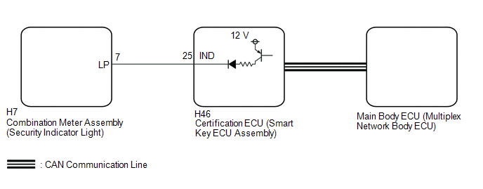
- The certification ECU (smart key ECU assembly) blinks the security indicator light (combination meter assembly) when the immobiliser is set (engine switch off).
- The certification ECU (smart key ECU assembly) receives the security indicator light signal from the main body ECU (multiplex network body ECU) via CAN communication when the theft deterrent system is in the arming preparation state or alarm sounding state. Then, the certification ECU (smart key ECU assembly) blinks the security indicator light (combination meter assembly).
WIRING DIAGRAM
CAUTION / NOTICE / HINT
NOTICE:
- When using the GTS with the ignition switch off, connect the GTS to the DLC3 and turn a courtesy light switch on and off at intervals of 1.5 seconds or less until communication between the GTS and the vehicle begins. Then select the vehicle type under manual mode and enter the following menus: Body Electrical / Smart Key. While using the GTS, periodically turn a courtesy light switch on and off at intervals of 1.5 seconds or less to maintain communication between the GTS and the vehicle.
-
The smart key system (for Start Function) uses the LIN communication system and CAN communication system. Inspect the communication function by following How to Proceed with Troubleshooting. Troubleshoot the smart key system (for Start Function) after confirming that the communication systems are functioning properly.
Click here

-
Before replacing the certification ECU (smart key ECU assembly) or main body ECU (multiplex network body ECU), refer to the Registration.
Click here

- Make sure that no DTCs are output. If any DTCs are output, proceed to the Diagnostic Trouble Code Chart.
- After completing repairs, confirm that the problem does not recur.
- After repair, confirm that no DTCs are output by performing "DTC Output Confirmation Operation".
- When replacing the combination meter assembly, always replace it with a new one. If a combination meter assembly which was installed to another vehicle is used, the information stored in it will not match the information from the vehicle and a DTC may be stored.
PROCEDURE
| 1. | CHECK FOR DTC |
(a) Check for DTCs.
Body Electrical > Smart Key > Trouble Codes Powertrain > Engine > Trouble CodesOK:
DTCs are not output.
| NG |
 | GO TO DIAGNOSTIC TROUBLE CODE CHART |
|

| 2. | PERFORM ACTIVE TEST USING GTS (IMMOBILISER INDICATOR) |
(a) Perform the Active Test according to the display on the GTS.
Body Electrical > Smart Key > Active Test| Tester Display | Measurement Item | Control Range | Diagnostic Note |
|---|---|---|---|
| Immobiliser Indicator | Security indicator light | OFF/ON | - |
| Tester Display |
|---|
| Immobiliser Indicator |
OK:
The security indicator light (combination meter assembly) operates normally.
| NG |
 | GO TO STEP 4 |
|

| 3. | CHECK SECURITY INDICATOR LIGHT (COMBINATION METER ASSEMBLY) OPERATION |
(a) When the immobiliser is set, check that the security indicator light (combination meter assembly) blinks.*1
OK:
The security indicator light (combination meter assembly) blinks normally.
(b) When the theft deterrent system is in the arming preparation state, check that the security indicator light (combination meter assembly) illuminates.*2
OK:
The security indicator light (combination meter assembly) illuminates normally.
| Result | Proceed to |
|---|---|
| *1 is NG (*2 is OK) | A |
| *2 is NG (*1 is OK) | B |
| A |
 | REPLACE CERTIFICATION ECU (SMART KEY ECU ASSEMBLY) |
| B |
 | REPLACE MAIN BODY ECU (MULTIPLEX NETWORK BODY ECU) |
| 4. | CHECK HARNESS AND CONNECTOR (CERTIFICATION ECU (SMART KEY ECU ASSEMBLY) - SECURITY INDICATOR LIGHT (COMBINATION METER ASSEMBLY)) |
(a) Disconnect the H46 certification ECU (smart key ECU assembly) connector.
(b) Disconnect the H7 combination meter assembly connector.
(c) Measure the resistance according to the value(s) in the table below.
Standard Resistance:
| Tester Connection | Condition | Specified Condition |
|---|---|---|
| H46-25 (IND) - H7-7 (LP) | Always | Below 1 Ω |
| H46-25 (IND) or H7-7 (LP) - Other terminals and body ground | Always | 10 kΩ or higher |
| NG |
 | REPAIR OR REPLACE HARNESS OR CONNECTOR |
|

| 5. | CHECK CERTIFICATION ECU (SMART KEY ECU ASSEMBLY) |
(a) Reconnect the H46 certification ECU (smart key ECU assembly) connector.
(b) Reconnect the H7 combination meter assembly connector.
(c) Using an oscilloscope, check the waveform.
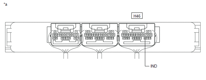
| *a | Component with harness connected (Certification ECU (Smart Key ECU Assembly)) | - | - |
Measurement Condition:
| Tester Connection | Switch Condition | Specified Condition |
|---|---|---|
| H46-25 (IND) - Body ground | Ignition switch off → ON | Pulse generation → Below 2 V |
| OK |
 | REPLACE SECURITY INDICATOR LIGHT (COMBINATION METER ASSEMBLY) |
| NG |
 | REPLACE CERTIFICATION ECU (SMART KEY ECU ASSEMBLY) |
 Steering Lock does not Lock
DESCRIPTION The steering lock ECU (steering lock actuator or upper bracket assembly) activates the steering lock motor and moves the lock bar into the steering column to lock the steering...
 Immobiliser System does not Operate Properly
DESCRIPTION The immobiliser function compares the ID code that is registered in the certification ECU (smart key ECU assembly) with the ID code of the transponder chip that is embedded in the electrical key transmitter sub-assembly...
Other information:
Toyota Yaris XP210 (2020-2026) Reapir and Service Manual: Initialization
INITIALIZATION SERVO MOTOR INITIALIZATION (a) Press the OFF switch. (b) According to the GTS display, perform servo motor initialization. Body Electrical > Air Conditioner > Utility Tester Display Servomotor Initialization HINT: When initialization is started, the AUTO switch indicator will illuminate and then will turn off when initialization has completed...
Toyota Yaris XP210 (2020-2026) Reapir and Service Manual: Reassembly
REASSEMBLY PROCEDURE 1. INSTALL ANTENNA CORD SUB-ASSEMBLY Click here 2. INSTALL INSTRUMENT PANEL PASSENGER WITHOUT DOOR AIRBAG ASSEMBLY Click here 3. INSTALL NO. 2 INSTRUMENT PANEL WIRE Click here 4. INSTALL INSTRUMENT CLUSTER FINISH PANEL ORNAMENT (a) Engage the guide and claws to install the instrument cluster finish panel ornament...
Categories
- Manuals Home
- Toyota Yaris Owners Manual
- Toyota Yaris Service Manual
- Battery Monitor Module General Electrical Failure (P058A01)
- Key Battery Replacement
- Removal
- New on site
- Most important about car
Key Suspend Function
If a key is left in the vehicle, the functions of the key left in the vehicle are temporarily suspended to prevent theft of the vehicle.
To restore the functions, press the unlock button on the functions-suspended key in the vehicle.