Toyota Yaris: Clutch Stroke Sensor / Removal
REMOVAL
PROCEDURE
1. REMOVE NO. 1 INSTRUMENT PANEL UNDER COVER SUB-ASSEMBLY
Click here

2. REMOVE BRAKE PEDAL RETURN SPRING
Click here

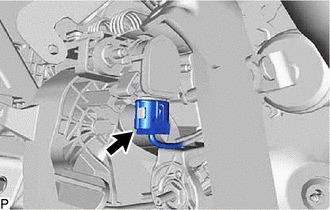
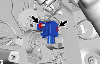
3. REMOVE CLUTCH PEDAL STROKE SENSOR ASSEMBLY
| (a) Disconnect the clutch pedal stroke sensor assembly connector. |
|
| (b) Remove the 2 nuts and clutch pedal stroke sensor assembly from the clutch pedal support assembly. NOTICE:
|
|
 On-vehicle Inspection
ON-VEHICLE INSPECTION PROCEDURE 1. INSPECT CLUTCH PEDAL STROKE SENSOR ASSEMBLY (a) Connect the GTS to the DLC3. (b) Turn the ignition switch to ON. (c) Turn the GTS on...
 Installation
INSTALLATION PROCEDURE 1. INSTALL CLUTCH PEDAL STROKE SENSOR ASSEMBLY (a) When installing a new clutch pedal stroke sensor assembly: NOTICE: Do not break the clutch pedal stroke sensor assembly lever set pin before being instructed to do so...
Other information:
Toyota Yaris XP210 (2020-2026) Reapir and Service Manual: G16e-gts Drive Belt
ComponentsCOMPONENTS ILLUSTRATION *1 FAN AND GENERATOR V BELT *2 ENGINE UNDER COVER RH *3 NO. 1 ENGINE UNDER COVER ASSEMBLY - - N*m (kgf*cm, ft.*lbf): Specified torque - - RemovalREMOVAL CAUTION / NOTICE / HINT HINT: Use a Toyota genuine belt or an equivalent high strength belt when replacing the belt...
Toyota Yaris XP210 (2020-2026) Reapir and Service Manual: Installation
INSTALLATION PROCEDURE 1. INSTALL FRONT BUMPER ASSEMBLY (a) Install the 3 grommets. HINT: Use the same procedure for the RH side and LH side. (b) Temporarily install the front bumper assembly with the 2 clips and 2 bolts. (c) w/ Pre-collision System: (1) Connect the connector...
Categories
- Manuals Home
- Toyota Yaris Owners Manual
- Toyota Yaris Service Manual
- Key Battery Replacement
- Brake System Control Module "A" System Voltage System Voltage Low (C137BA2)
- G16e-gts (engine Mechanical)
- New on site
- Most important about car
Fuel Gauge
The fuel gauge shows approximately how much fuel is remaining in the tank when the ignition is switched ON. We recommend keeping the tank over 1/4 full.

Copyright © 2026 www.toyaris4.com