Toyota Yaris: Clutch Stroke Sensor / Installation
INSTALLATION
PROCEDURE
1. INSTALL CLUTCH PEDAL STROKE SENSOR ASSEMBLY
(a) When installing a new clutch pedal stroke sensor assembly:
NOTICE:
Do not break the clutch pedal stroke sensor assembly lever set pin before being instructed to do so.
| (1) Install a new clutch pedal stroke sensor assembly to the clutch pedal support assembly with the 2 nuts. Torque: 8.5 N·m {87 kgf·cm, 75 in·lbf} NOTICE:
|
|
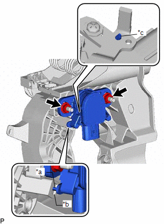
(2) Connect the clutch pedal stroke sensor assembly connector.
(3) Firmly depress the clutch pedal sub-assembly to break the clutch pedal stroke sensor assembly lever set pin.
(4) Remove the broken clutch pedal stroke sensor assembly lever set pin.
(b) When reusing the clutch pedal stroke sensor assembly:
| (1) Install the clutch pedal stroke sensor assembly to the clutch pedal support assembly and temporarily tighten the 2 nuts. NOTICE:
HINT: When fully tightening the nuts, perform Adjust Clutch Pedal Stroke Sensor Assembly first. |
|
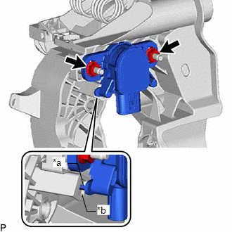
(2) Connect the clutch pedal stroke sensor assembly connector.
2. CONNECT CABLE TO NEGATIVE AUXILIARY BATTERY TERMINAL
Click here

3. ADJUST CLUTCH PEDAL STROKE SENSOR ASSEMBLY
NOTICE:
When the clutch pedal stroke sensor assembly is being reused, perform the following procedure to adjust it.
(a) Connect the GTS to the DLC3 with the ignition switch off.
(b) Turn the ignition switch to ON.
(c) Turn the GTS on.
(d) Enter the following menus: Powertrain / Engine / Data List / Clutch Stroke Sensor Voltage.
Powertrain > Engine > Data List| Tester Display |
|---|
| Clutch Stroke Sensor Voltage |
| (e) Read the stroke sensor value in the Data List, and turn the clutch pedal stroke sensor assembly slowly to the right or left to adjust the output voltage so that it is within the following range. Standard Voltage (clutch pedal fully released): 0.96 to 1.04 V |
|
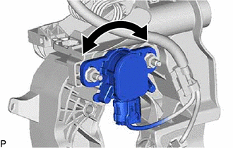
(f) Tighten the 2 nuts.
Torque:
8.5 N·m {87 kgf·cm, 75 in·lbf}
NOTICE:
After turning the ignition switch to ON, do not depress the clutch pedal sub-assembly until the nuts have been tightened.
(g) Turn the GTS off and turn the ignition switch off.
(h) Disconnect the GTS from the DLC3.
4. INSTALL BRAKE PEDAL RETURN SPRING
Click here

5. INSTALL NO. 1 INSTRUMENT PANEL UNDER COVER SUB-ASSEMBLY
Click here

6. CHECK AND CLEAR DTC
Click here

 Removal
REMOVAL PROCEDURE 1. REMOVE NO. 1 INSTRUMENT PANEL UNDER COVER SUB-ASSEMBLY Click here
2. REMOVE BRAKE PEDAL RETURN SPRING Click here
3. REMOVE CLUTCH PEDAL STROKE SENSOR ASSEMBLY (a) Disconnect the clutch pedal stroke sensor assembly connector...

Other information:
Toyota Yaris XP210 (2020-2026) Reapir and Service Manual: Parts Location
PARTS LOCATION ILLUSTRATION *1 WINDSHIELD WIPER MOTOR ASSEMBLY *2 WINDSHIELD WASHER MOTOR AND PUMP ASSEMBLY *3 NO. 1 ENGINE ROOM RELAY BLOCK AND NO. 1 JUNCTION BLOCK ASSEMBLY - WIPER FUSE - WASHER FUSE - WIPER RELAY *4 RAIN SENSOR ILLUSTRATION *1 STEERING WHEEL SWITCH HOUSING *2 WINDSHIELD WIPER SWITCH ASSEMBLY *3 STEERING SENSOR *4 WINDSHIELD WIPER RELAY ASSEMBLY *5 MAIN BODY ECU (MULTIPLEX NETWORK BODY ECU) *6 POWER DISTRIBUTION BOX ASSEMBLY - WIPER RR FUSE - ECU-IGR NO...
Toyota Yaris XP210 (2020-2026) Reapir and Service Manual: Installation
INSTALLATION CAUTION / NOTICE / HINT CAUTION: Wear protective gloves. Sharp areas on the parts may injure your hands. There is risk of injury. HINT: Use the same procedure for the driver side and front passenger side. The procedure listed below is for the driver side...
Categories
- Manuals Home
- Toyota Yaris Owners Manual
- Toyota Yaris Service Manual
- Diagnostic Trouble Code Chart
- Maintenance
- Immobilizer System
- New on site
- Most important about car
Break-In Period
No special break-in is necessary, but a few precautions in the first 600 miles (1,000 km) may add to the performance, economy, and life of the vehicle.
Do not race the engine. Do not maintain one constant speed, either slow or fast, for a long period of time. Do not drive constantly at full-throttle or high engine rpm for extended periods of time. Avoid unnecessary hard stops. Avoid full-throttle starts.