Toyota Yaris: Rear Lower Arm / Removal
REMOVAL
CAUTION / NOTICE / HINT
The necessary procedures (adjustment, calibration, initialization, or registration) that must be performed after parts are removed and installed, or replaced during rear suspension arm assembly removal/installation are shown below.
Necessary Procedures After Parts Removed/Installed/Replaced| Replaced Part or Performed Procedure | Necessary Procedure | Effect/Inoperative Function when Necessary Procedure not Performed | Link |
|---|---|---|---|
| Rear wheel alignment adjustment | ECU Data Initialization | Active torque split AWD system |
|
| Calibration |
|
|


HINT:
- Use the same procedure for the RH side and LH side.
- The following procedure is for the LH side.
PROCEDURE
1. REMOVE REAR WHEEL
Click here

2. REMOVE REAR STABILIZER LINK ASSEMBLY
Click here

3. REMOVE REAR COIL SPRING
Click here

4. REMOVE REAR LOWER COIL SPRING INSULATOR
Click here

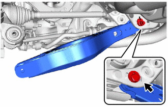
5. REMOVE REAR NO. 2 SUSPENSION ARM ASSEMBLY
| (a) Remove the nut, No. 2 camber adjust cam, rear suspension toe adjust cam sub-assembly and rear No. 2 suspension arm assembly. NOTICE: Hold the rear suspension toe adjust cam sub-assembly while rotating the nut. |
|
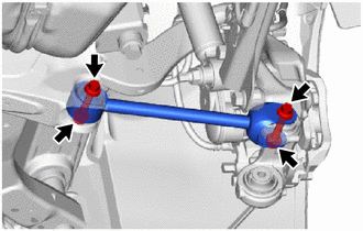
6. REMOVE REAR NO. 1 SUSPENSION ARM ASSEMBLY
| (a) Remove the 2 bolts, 2 nuts and rear No. 1 suspension arm assembly from the rear axle carrier sub-assembly and rear suspension member sub-assembly. NOTICE: Loosen the bolt with the nut secured. |
|
 Components
COMPONENTS ILLUSTRATION
*1 REAR COIL SPRING *2 REAR LOWER COIL SPRING INSULATOR *3 REAR NO. 2 SUSPENSION ARM ASSEMBLY *4 REAR STABILIZER LINK ASSEMBLY *5 REAR STABILIZER BAR *6 REAR SUSPENSION TOE ADJUST CAM SUB-ASSEMBLY *7 NO...
 Installation
INSTALLATION CAUTION / NOTICE / HINT HINT:
Use the same procedure for the RH side and LH side.
The following procedure is for the LH side.
PROCEDURE 1...
Other information:
Toyota Yaris XP210 (2020-2026) Reapir and Service Manual: All Door Entry Lock/Unlock Functions do not Operate, but Wireless Functions Operate
DESCRIPTION When the wireless operation can be used to lock and unlock the doors, communication between the smart door control receiver assembly and certification ECU (smart key ECU assembly) is normal. If the entry lock and unlock functions do not operate, the entry cancel function may be set through the customize function, there may be communication problems between the electrical key transmitter sub-assembly and vehicle, or there may be wave interference...
Toyota Yaris XP210 (2020-2026) Reapir and Service Manual: Front Recognition Camera Optical Axis Misalignment Malfunction (C1AA800)
DESCRIPTION The forward recognition camera monitors its optical axis status. If it determines that the optical axis alignment has become misaligned, it will store DTC C1AA800. DTC No. Detection Item DTC Detection Condition Trouble Area C1AA800 Front Recognition Camera Optical Axis Misalignment Malfunction When the forward recognition camera detects an optical axis misalignment when the vehicle is being driven at a speed of 5 km/h (4 mph) or more, after 2 seconds have elapsed since the ignition switch was turned ON...
Categories
- Manuals Home
- Toyota Yaris Owners Manual
- Toyota Yaris Service Manual
- Fuel Gauge
- Opening and Closing the Liftgate/Trunk Lid
- Fuse Panel Description
- New on site
- Most important about car
Fuel Gauge
The fuel gauge shows approximately how much fuel is remaining in the tank when the ignition is switched ON. We recommend keeping the tank over 1/4 full.
