
Toyota Yaris: Rear Lower Arm / Installation
INSTALLATION
CAUTION / NOTICE / HINT
HINT:
- Use the same procedure for the RH side and LH side.
- The following procedure is for the LH side.
PROCEDURE
1. TEMPORARILY INSTALL REAR NO. 1 SUSPENSION ARM ASSEMBLY
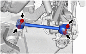
(a) Temporarily install the rear No. 1 suspension arm assembly to the rear axle carrier sub-assembly and rear suspension member sub-assembly with the 2 bolts and 2 nuts.
NOTICE:
- Tighten the bolt with the nut secured.
- Insert the bolt with the threaded end facing the front of the vehicle.
2. TEMPORARILY INSTALL REAR NO. 2 SUSPENSION ARM ASSEMBLY
(a) Temporarily install the rear No. 2 suspension arm assembly to the rear suspension member sub-assembly with the No. 2 camber adjust cam, rear suspension toe adjust cam sub-assembly and nut.
NOTICE:
- Insert the rear suspension toe adjust cam sub-assembly from the front of the vehicle.
- When tightening the nut, keep the rear suspension toe adjust cam sub-assembly from rotating.
3. INSTALL REAR LOWER COIL SPRING INSULATOR
Click here

4. INSTALL REAR COIL SPRING
Click here

5. STABILIZE SUSPENSION
Click here

6. INSTALL REAR STABILIZER LINK ASSEMBLY
Click here

7. FULLY TIGHTEN REAR NO. 1 SUSPENSION ARM ASSEMBLY
| (a) Install the rear No. 1 suspension arm assembly with the 2 bolts. Torque: 73 N·m {744 kgf·cm, 54 ft·lbf} NOTICE: Tighten the bolt with the nut secured. |
|
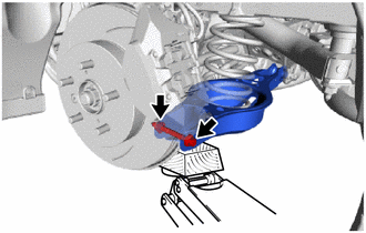
8. FULLY TIGHTEN REAR NO. 2 SUSPENSION ARM ASSEMBLY
| (a) Install the rear No. 2 suspension arm assembly (rear axle carrier sub-assembly side) with the bolt. Torque: 73 N·m {744 kgf·cm, 54 ft·lbf} NOTICE: Tighten the bolt with the nut secured. |
|
9. INSTALL REAR WHEEL
Click here

10. FULLY TIGHTEN REAR NO. 2 SUSPENSION ARM ASSEMBLY
(a) Lower the vehicle to the ground.
(b) Bounce the vehicle up and down at the corners to stabilize the rear suspension.
| (c) Align the matchmarks on the No. 2 camber adjust cam, rear suspension toe adjust cam sub-assembly and rear suspension member sub-assembly. |
|
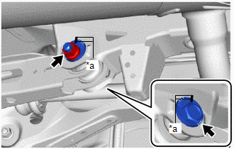
(d) Fully tighten the nut.
Torque:
100 N·m {1020 kgf·cm, 74 ft·lbf}
NOTICE:
- Hold the rear suspension toe adjust cam sub-assembly while rotating the nut.
- Make sure that the vehicle is unloaded when fully tightening the nut.
11. INSPECT AND ADJUST REAR WHEEL ALIGNMENT
Click here

 Removal
REMOVAL CAUTION / NOTICE / HINT The necessary procedures (adjustment, calibration, initialization, or registration) that must be performed after parts are removed and installed, or replaced during rear suspension arm assembly removal/installation are shown below...

Other information:
Toyota Yaris XP210 (2020-2026) Reapir and Service Manual: Removal
REMOVAL CAUTION / NOTICE / HINT The necessary procedures (adjustment, calibration, initialization or registration) that must be performed after parts are removed and installed, or replaced during the windshield glass removal/installation are shown below...
Toyota Yaris XP210 (2020-2026) Reapir and Service Manual: On-vehicle Inspection
ON-VEHICLE INSPECTION PROCEDURE 1. INSPECT CLUTCH PEDAL STROKE SENSOR ASSEMBLY (a) Connect the GTS to the DLC3. (b) Turn the ignition switch to ON. (c) Turn the GTS on. (d) Enter the following menus: Powertrain / Engine / Data List / Clutch Stroke Sensor Voltage...
Categories
- Manuals Home
- Toyota Yaris Owners Manual
- Toyota Yaris Service Manual
- Power Integration No.1 System Missing Message (B235287,B235587,B235787-B235987)
- Immobilizer System
- Diagnostic Trouble Code Chart
- New on site
- Most important about car
Break-In Period
No special break-in is necessary, but a few precautions in the first 600 miles (1,000 km) may add to the performance, economy, and life of the vehicle.
Do not race the engine. Do not maintain one constant speed, either slow or fast, for a long period of time. Do not drive constantly at full-throttle or high engine rpm for extended periods of time. Avoid unnecessary hard stops. Avoid full-throttle starts.