Toyota Yaris: Smart Key System (for Start Function) / Power Source Mode does not Change to ON (IG and ACC)
DESCRIPTION
When the ignition switch cannot be turned to ACC or ON, interior verification may be abnormal or there may be a malfunction in the ACC relay or IG relay circuit. If interior verification cannot be performed, the certification ECU (smart key ECU assembly) may be malfunctioning or communication may not be possible between the No. 1 indoor electrical key antenna assembly (front floor), No. 2 indoor electrical key antenna assembly (rear floor) and the electrical key transmitter sub-assembly and smart door control receiver assembly.
When an electrical key transmitter sub-assembly is brought into the cabin, its key ID code is compared with the key ID code stored in the certification ECU (smart key ECU assembly). If these codes do not match, key verification will fail and the ignition switch will not be able to be turned to ACC or ON.
When a door is unlocked and an electrical key transmitter sub-assembly is brought into the cabin, the certification ECU (smart key ECU assembly) activates the indoor electrical key antenna assemblies to form the interior detection area. The electrical key transmitter sub-assembly then responds to the detection signals with its key ID code. This response signal is received by the smart door control receiver assembly and sent to the certification ECU (smart key ECU assembly).
Related Data List and Active Test Items| Problem Symptom | Data List and Active Test |
|---|---|
| Power source mode does not change to on (IG) or on (ACC) | Power Source Control
|
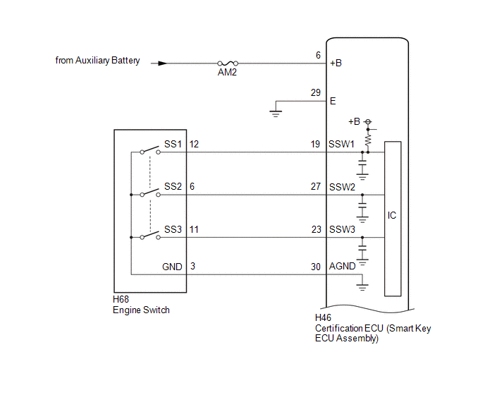
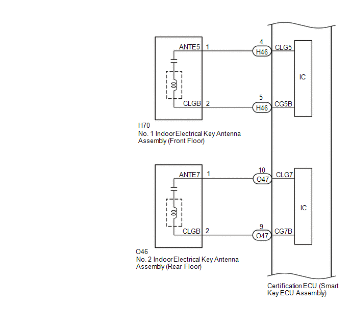
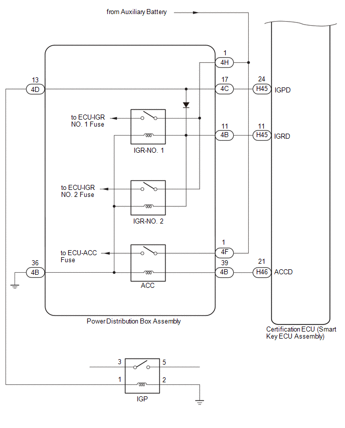
WIRING DIAGRAM
CAUTION / NOTICE / HINT
NOTICE:
- When using the GTS with the ignition switch off, connect the GTS to the DLC3 and turn a courtesy light switch on and off at intervals of 1.5 seconds or less until communication between the GTS and the vehicle begins. Then select the vehicle type under manual mode and enter the following menus: Body Electrical / Smart Key. While using the GTS, periodically turn a courtesy light switch on and off at intervals of 1.5 seconds or less to maintain communication between the GTS and the vehicle.
-
The smart key system (for Start Function) uses the LIN communication system and CAN communication system. Inspect the communication function by following How to Proceed with Troubleshooting. Troubleshoot the smart key system (for Start Function) after confirming that the communication systems are functioning properly.
Click here

- Make sure that no DTCs are output. If any DTCs are output, proceed to Diagnostic Trouble Code Chart.
-
If the smart key system (for Start Function) has been disabled, enable the system before performing troubleshooting.
Click here

- Inspect the fuses for circuits related to this system before performing the following procedure.
-
Before replacing the certification ECU (smart key ECU assembly) or an electrical key transmitter sub-assembly, refer to Registration.
Click here

- After completing repairs, confirm that the problem does not recur.
- After performing repairs, confirm that no DTCs are output by performing "DTC Output Confirmation Operation."
- The indoor electrical key antenna assemblies have an antenna coil between each terminal.
- The smart door control receiver assembly is also related to interior certification.
HINT:
- If interior verification is unsuccessful, Vehicle Control History may be stored.
- If Vehicle Control History has been stored, refer to the Vehicle Control History List to determine the detection conditions and narrow down trouble areas.
| Tester Display |
|---|
| Vehicle Control History (RoB) |
PROCEDURE
| 1. | CHECK POWER SOURCE MODE |
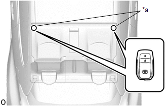
(a) Get into the vehicle while carrying the electrical key transmitter sub-assembly that has already been registered.
(b) Press the engine switch with the clutch pedal released and check that the power source mode changes.
Click here

| Result | Proceed to |
|---|---|
| Power source mode cannot be changed when electrical key transmitter sub-assembly is in push button start function operation range for front side | A |
| Power source mode cannot be changed when electrical key transmitter sub-assembly is in push button start function operation range for rear side | B |
| Power source mode cannot be changed | C |
| B |
 | GO TO STEP 6 |
| C |
 | GO TO STEP 10 |
|

| 2. | CHECK WAVE ENVIRONMENT |
(a) Install the transmitter battery to the electrical key transmitter sub-assembly.
Click here

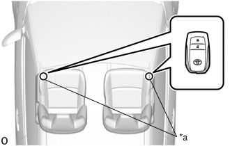
(b) Bring the electrical key transmitter sub-assembly near the No. 1 indoor electrical key antenna assembly (front floor) and perform a smart key system check.
Click here

NOTICE:
Communication may not be possible if the electrical key transmitter sub-assembly is within 0.2 m (0.656 ft.) of the No. 1 indoor electrical key antenna assembly (front floor).
HINT:
- As the effect of wave interference decreases by moving the electrical key transmitter sub-assembly close to each indoor electrical key antenna assembly, it may be possible to check whether wave interference is the cause of the problem.
- If the inspection result is that the problem only occurs in certain locations or at certain times of day, the possibility of wave interference is high. Also, added vehicle components may cause wave interference. If installed, remove them and perform the operation check.
- There may be wave interference if the vehicle is near broadcasting antennas, large video displays, wireless garage door opener systems, wireless security cameras, home security systems, etc. In this case, move the vehicle to a different location and check if there is any improvement.
- If a tool for checking radio waves, such as a signal strength meter, is available, move around the area while observing both the LF band (used by the vehicle antenna to form the detection area) and RF band (used by the electrical key transmitter sub-assembly for transmission) to check for locations where there is wave interference.
OK:
The engine starts when the electrical key transmitter sub-assembly is held near each indoor electrical key antenna assembly and the engine switch is pressed with the clutch pedal depressed.
| OK |
 | AFFECTED BY WAVE INTERFERENCE |
|

| 3. | CHECK KEY DIAGNOSTIC MODE |
(a) Check the following antennas in key diagnostic mode.
| (b) Check the No. 1 indoor electrical key antenna assembly (front floor). When the electrical key transmitter sub-assembly is at either inspection point, check that the wireless buzzer sounds. HINT:
|
|
| Result | Proceed to |
|---|---|
| The wireless buzzer does not sound | A |
| The wireless buzzer sounds | B |
| B |
 | AFFECTED BY WAVE INTERFERENCE |
|

| 4. | CHECK HARNESS AND CONNECTOR (CERTIFICATION ECU (SMART KEY ECU ASSEMBLY) - NO. 1 INDOOR ELECTRICAL KEY ANTENNA ASSEMBLY (FRONT FLOOR)) |
(a) Disconnect the H46 certification ECU (smart key ECU assembly) connector.
(b) Disconnect the H70 No. 1 indoor electrical key antenna assembly (front floor) connector.
(c) Measure the resistance according to the value(s) in the table below.
Standard Resistance:
| Tester Connection | Condition | Specified Condition |
|---|---|---|
| H46-4 (CLG5) - H70-1 (ANTE5) | Always | Below 1 Ω |
| H46-5 (CG5B) - H70-2 (CLGB) | Always | Below 1 Ω |
| H46-4 (CLG5) or H70-1 (ANTE5) - Other terminals and body ground | Always | 10 kΩ or higher |
| H46-5 (CG5B) or H70-2 (CLGB) - Other terminals and body ground | Always | 10 kΩ or higher |
(d) Reconnect the H46 certification ECU (smart key ECU assembly) connector.
| NG |
 | REPAIR OR REPLACE HARNESS OR CONNECTOR |
|

| 5. | CHECK CERTIFICATION ECU (SMART KEY ECU ASSEMBLY) (OUTPUT TO NO. 1 INDOOR ELECTRICAL KEY ANTENNA ASSEMBLY (FRONT FLOOR)) |
(a) Using an oscilloscope, check the waveform.
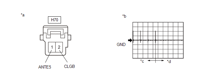
| *a | Front view of wire harness connector (to No. 1 Indoor Electrical Key Antenna Assembly (Front Floor)) | *b | Waveform |
| *c | For 30 seconds after closing any door | *d | After 30 seconds or more have elapsed since any door closed |
OK:
| Tester Connection | Condition | Tool Setting | Specified Condition |
|---|---|---|---|
| H70-1 (ANTE5) - H70-2 (CLGB) | Procedure:
| 5 V/DIV., 500 ms./DIV. | Pulse generation (See waveform) |
| OK |
 | REPLACE NO. 1 INDOOR ELECTRICAL KEY ANTENNA ASSEMBLY (FRONT FLOOR) |
| NG |
 | REPLACE CERTIFICATION ECU (SMART KEY ECU ASSEMBLY) |
| 6. | CHECK WAVE ENVIRONMENT |
(a) Install the transmitter battery to the electrical key transmitter sub-assembly.
Click here

(b) Bring the electrical key transmitter sub-assembly near the No. 2 indoor electrical key antenna assembly (rear floor) and perform a smart key system check.
Click here

NOTICE:
Communication may not be possible if the electrical key transmitter sub-assembly is within 0.2 m (0.656 ft.) of the center of the No. 2 indoor electrical key antenna assembly (rear floor).
HINT:
- Check that the customize setting "Ignition Available Area" is set to "All".
- As the effect of wave interference decreases by moving the electrical key transmitter sub-assembly close to each indoor electrical key antenna assembly, it may be possible to check whether wave interference is the cause of the problem.
- If the inspection result is that the problem only occurs in certain locations or at certain times of day, the possibility of wave interference is high. Also, added vehicle components may cause wave interference. If installed, remove them and perform the operation check.
- There may be wave interference if the vehicle is near broadcasting antennas, large video displays, wireless garage door opener systems, wireless security cameras, home security systems, etc. In this case, move the vehicle to a different location and check if there is any improvement.
- If a tool for checking radio waves, such as a signal strength meter, is available, move around the area while observing both the LF band (used by the vehicle antenna to form the detection area) and RF band (used by the electrical key transmitter sub-assembly for transmission) to check for locations where there is wave interference.
OK:
The engine starts when the electrical key transmitter sub-assembly is held near each indoor electrical key antenna assembly and the engine switch is pressed with the clutch pedal depressed.
| OK |
 | AFFECTED BY WAVE INTERFERENCE |
|

| 7. | CHECK KEY DIAGNOSTIC MODE |
(a) Check the following antennas in key diagnostic mode.
| (b) Check the No. 2 indoor electrical key antenna assembly (rear floor). When the electrical key transmitter sub-assembly is at either inspection point, check that the wireless buzzer sounds. HINT:
|
|
| Result | Proceed to |
|---|---|
| The wireless buzzer does not sound | A |
| The wireless buzzer sounds | B |
| B |
 | AFFECTED BY WAVE INTERFERENCE |
|

| 8. | CHECK HARNESS AND CONNECTOR (CERTIFICATION ECU (SMART KEY ECU ASSEMBLY) - NO. 2 INDOOR ELECTRICAL KEY ANTENNA ASSEMBLY (REAR FLOOR)) |
(a) Disconnect the O47 certification ECU (smart key ECU assembly) connector.
(b) Disconnect the O46 No. 2 indoor electrical key antenna assembly (rear floor) connector.
(c) Measure the resistance according to the value(s) in the table below.
Standard Resistance:
| Tester Connection | Condition | Specified Condition |
|---|---|---|
| O47-10 (CLG7) - O46-1 (ANTE7) | Always | Below 1 Ω |
| O47-9 (CG7B) - O46-2 (CLGB) | Always | Below 1 Ω |
| O47-10 (CLG7) or O46-1 (ANTE7) - Other terminals and body ground | Always | 10 kΩ or higher |
| O47-9 (CG7B) or O46-2 (CLGB) - Other terminals and body ground | Always | 10 kΩ or higher |
(d) Reconnect the O47 certification ECU (smart key ECU assembly) connector.
| NG |
 | REPAIR OR REPLACE HARNESS OR CONNECTOR |
|

| 9. | CHECK CERTIFICATION ECU (SMART KEY ECU ASSEMBLY) (OUTPUT TO NO. 2 INDOOR ELECTRICAL KEY ANTENNA ASSEMBLY (REAR FLOOR)) |
(a) Using an oscilloscope, check the waveform.

| *a | Front view of wire harness connector (to No. 2 Indoor Electrical Key Antenna Assembly (Rear Floor)) | *b | Waveform |
| *c | For 30 seconds after closing any door | *d | After 30 seconds or more have elapsed since any door closed |
OK:
| Tester Connection | Condition | Tool Setting | Specified Condition |
|---|---|---|---|
| O46-1 (ANTE7) - O46-2 (CLGB) | Procedure:
| 5 V/DIV., 500 ms./DIV. | Pulse generation (See waveform) |
| OK |
 | REPLACE NO. 2 INDOOR ELECTRICAL KEY ANTENNA ASSEMBLY (REAR FLOOR) |
| NG |
 | REPLACE CERTIFICATION ECU (SMART KEY ECU ASSEMBLY) |
| 10. | INSPECT TRANSMITTER BATTERY |
(a) Check the transmitter battery level of the electrical key transmitter sub-assembly that was checked first.
(1) Press and hold the lock switch of the electrical key transmitter sub-assembly for 5 seconds and check the number of times that the LED illuminates.
HINT:
-
The electrical key transmitter sub-assembly sends voltage information to the certification ECU (smart key ECU assembly) when it is being used. "Yes" is displayed for the Data List item Key Low Battery when this voltage information indicates 2.2 V or less.
Click here

- Even if the transmitter battery is depleted, it is still possible to start the engine by holding the electrical key transmitter sub-assembly near the engine switch, depressing the clutch pedal and pressing the engine switch.
| Result | Proceed to |
|---|---|
| LED illuminates 3 times or more when switch is pressed and held | A |
| LED does not illuminate when switch is pressed and held | B |
| LED illuminates once or twice but not a third time | C |
| B |
 | GO TO STEP 17 |
| C |
 | REPLACE TRANSMITTER BATTERY |
|

| 11. | CHECK ENTRY LOCK / UNLOCK OPERATION |
(a) Check that the entry lock and unlock functions operate on each door.
Click here

HINT:
If the smart door control receiver assembly is defective, code verification does not begin in the cabin and the entry lock and unlock functions do not operate.
| Result | Proceed to |
|---|---|
| Entry functions operate normally for all doors | A |
| An entry function does not operate normally for a door | B |
| B |
 | GO TO ENTRY AND START SYSTEM (for Entry Function) (All Door Entry Lock/Unlock Functions and Wireless Functions do not Operate) |
|

| 12. | READ VALUE USING GTS (PUSH START SWITCH 1, PUSH START SWITCH 2, PUSH START SWITCH 3) |
(a) Read the Data List according to the display on the GTS.
Body Electrical > Power Source Control > Data List| Tester Display | Measurement Item | Range | Normal Condition | Diagnostic Note |
|---|---|---|---|---|
| Push Start Switch 1 | Engine switch 1 status | OFF or ON | OFF: Engine switch not pressed ON: Engine switch pressed |
|
| Push Start Switch 2 | Engine switch 2 status | OFF or ON | OFF: Engine switch not pressed ON: Engine switch pressed |
|
| Push Start Switch 3 | Engine switch 3 status | OFF or ON | OFF: Engine switch not pressed ON: Engine switch pressed |
|
| Tester Display |
|---|
| Push Start Switch 1 |
| Push Start Switch 2 |
| Push Start Switch 3 |
OK:
The value of "Start Switch1", "Start Switch2" and "Start Switch3" change correctly in response to the engine switch operation.
| NG |
 | GO TO STEP 15 |
|

| 13. | CHECK CERTIFICATION ECU (SMART KEY ECU ASSEMBLY) |
(a) Measure the voltage while checking the Data List on the GTS.
(1) Read the Data List according to the display on the GTS.
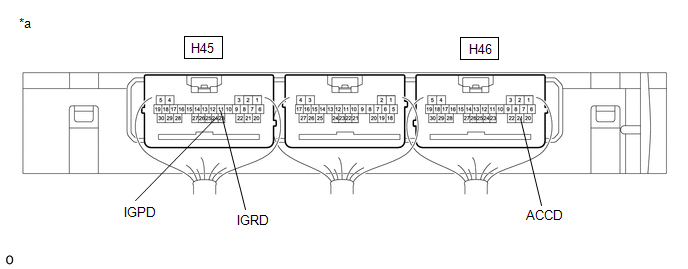
| *a | Component with harness connected (Certification ECU (Smart Key ECU Assembly)) | - | - |
| Tester Display | Measurement Item | Range | Normal Condition | Diagnostic Note |
|---|---|---|---|---|
| Power Supply Condition | Power supply state | OFF, ACC ON, IGR ON, IGP ON or Starter ON | OFF: Ignition switch off ACC ON: Ignition switch ACC IGR ON: Ignition switch ON IGP ON: Ignition switch ON Starter ON: Sending engine start request signal | - |
| Tester Display |
|---|
| Power Supply Condition |
(2) Measure the voltage according to the value(s) in the table below.
Standard Voltage:
| Tester Connection | Switch Condition | Specified Condition |
|---|---|---|
| H45-11 (IGRD) - Body ground | Ignition switch off | Below 1 V |
| Ignition switch ACC | Below 1 V | |
| Ignition switch ON | 9 V or higher | |
| H45-24 (IGPD) - Body ground | Ignition switch off | Below 1 V |
| Ignition switch ACC | Below 1 V | |
| Ignition switch ON | 9 V or higher | |
| H46-21 (ACCD) - Body ground | Ignition switch off | Below 1 V |
| Ignition switch ACC | 8.5 V or higher | |
| Ignition switch ON | 8.5 V or higher |
| NG |
 | REPLACE CERTIFICATION ECU (SMART KEY ECU ASSEMBLY) |
|

| 14. | CHECK HARNESS AND CONNECTOR (POWER DISTRIBUTION BOX ASSEMBLY - BODY GROUND) |
(a) Disconnect the 4B power distribution box assembly connector.
(b) Measure the resistance according to the value(s) in the table below.
Standard Resistance:
| Tester Connection | Condition | Specified Condition |
|---|---|---|
| 4B-36 - Body ground | Always | Below 1 Ω |
| OK |
 | REPLACE POWER DISTRIBUTION BOX ASSEMBLY |
| NG |
 | REPAIR OR REPLACE HARNESS OR CONNECTOR |
| 15. | INSPECT ENGINE SWITCH |
Click here

| NG |
 | REPLACE ENGINE SWITCH |
|

| 16. | CHECK HARNESS AND CONNECTOR (CERTIFICATION ECU (SMART KEY ECU ASSEMBLY) - ENGINE SWITCH) |
(a) Disconnect the H46 certification ECU (smart key ECU assembly) connector.
(b) Measure the resistance according to the value(s) in the table below.
Standard Resistance:
| Tester Connection | Condition | Specified Condition |
|---|---|---|
| H46-19 (SSW1) - H68-12 (SS1) | Always | Below 1 Ω |
| H46-27 (SSW2) - H68-6 (SS2) | Always | Below 1 Ω |
| H46-23 (SSW3) - H68-11 (SS3) | Always | Below 1 Ω |
| H46-30 (AGND) - H68-3 (GND) | Always | Below 1 Ω |
| H46-19 (SSW1) or H68-12 (SS1) - Other terminals and body ground | Always | 10 kΩ or higher |
| H46-27 (SSW2) or H68-6 (SS2) - Other terminals and body ground | Always | 10 kΩ or higher |
| H46-23 (SSW3) or H68-11 (SS3) - Other terminals and body ground | Always | 10 kΩ or higher |
| H46-30 (AGND) or H68-3 (GND) - Other terminals and body ground | Always | 10 kΩ or higher |
| OK |
 | REPLACE CERTIFICATION ECU (SMART KEY ECU ASSEMBLY) |
| NG |
 | REPAIR OR REPLACE HARNESS OR CONNECTOR |
| 17. | INSPECT TRANSMITTER BATTERY |
(a) Inspect the transmitter battery.
Click here

NOTICE:
Do not wrap the lead wire ground a terminal, wedge it between terminals, or solder it. The terminal may be deformed or damaged, and the transmitter battery will not be able to be installed correctly.
| OK |
 | REPLACE ELECTRICAL KEY TRANSMITTER SUB-ASSEMBLY |
| NG |
 | REPLACE TRANSMITTER BATTERY |
 Engine does not Start
DESCRIPTION When the electrical key transmitter sub-assembly is in the cabin and the engine switch is pressed, the certification ECU (smart key ECU assembly) receives a signal and changes the power source mode...
 Power Source Mode does not Change to ON (IG)
DESCRIPTION If the engine switch is pressed with the electrical key transmitter sub-assembly in the cabin, the certification ECU (smart key ECU assembly) receives a signal and changes the power source mode...
Other information:
Toyota Yaris XP210 (2020-2026) Reapir and Service Manual: Removal
REMOVAL PROCEDURE 1. RECOVER REFRIGERANT FROM REFRIGERATION SYSTEM Click here 2. REMOVE HEADLIGHT ASSEMBLY LH Click here 3. REMOVE HEADLIGHT ASSEMBLY RH HINT: Use the same procedure as for the LH side. 4. REMOVE NO. 1 AIR CLEANER INLET Click here 5...
Toyota Yaris XP210 (2020-2026) Reapir and Service Manual: Components
COMPONENTS ILLUSTRATION *1 NO. 1 ENGINE UNDER COVER ASSEMBLY - - N*m (kgf*cm, ft.*lbf): Specified torque - - ILLUSTRATION *1 WATER GUARD PLATE RH *2 NO. 1 FRONT VENTILATOR SEAL *3 OUTER COWL TOP PANEL SUB-ASSEMBLY - - N*m (kgf*cm, ft...
Categories
- Manuals Home
- Toyota Yaris Owners Manual
- Toyota Yaris Service Manual
- Immobilizer System
- Removal
- Adjustment
- New on site
- Most important about car
Fuel Gauge
The fuel gauge shows approximately how much fuel is remaining in the tank when the ignition is switched ON. We recommend keeping the tank over 1/4 full.
