Toyota Yaris: Smart Key System (for Start Function) / Power Source Mode does not Change to ON (IG)
DESCRIPTION
If the engine switch is pressed with the electrical key transmitter sub-assembly in the cabin, the certification ECU (smart key ECU assembly) receives a signal and changes the power source mode.
Related Data List and Active Test Items| Problem Symptom | Data List and Active Test |
|---|---|
| Power source mode does not change to on (IG) but does change to on (ACC) | Power Source Control
|
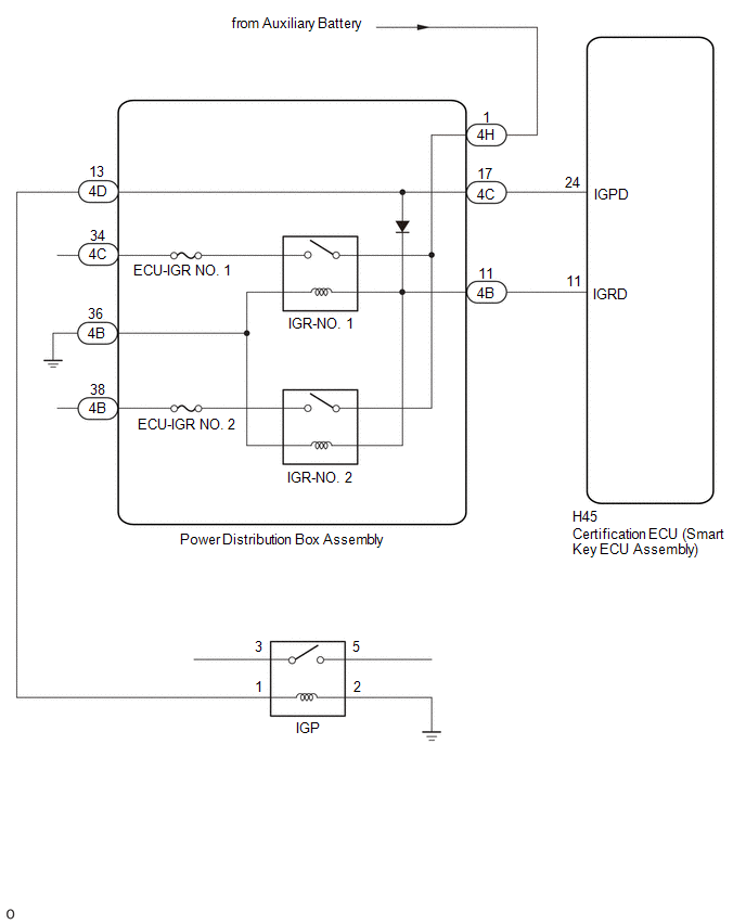
WIRING DIAGRAM
CAUTION / NOTICE / HINT
NOTICE:
- When using the GTS with the ignition switch off, connect the GTS to the DLC3 and turn a courtesy light switch on and off at intervals of 1.5 seconds or less until communication between the GTS and the vehicle begins. Then select the vehicle type under manual mode and enter the following menus: Body Electrical / Smart Key. While using the GTS, periodically turn a courtesy light switch on and off at intervals of 1.5 seconds or less to maintain communication between the GTS and the vehicle.
-
The smart key system (for Start Function) uses the LIN communication system and CAN communication system. Inspect the communication function by following How to Proceed with Troubleshooting. Troubleshoot the smart key system (for Start Function) after confirming that the communication systems are functioning properly.
Click here

- Make sure that no DTCs are output. If any DTCs are output, proceed to Diagnostic Trouble Code Chart.
-
If the smart key system (for Start Function) has been disabled, enable the system before performing troubleshooting.
Click here

- Inspect the fuses for circuits related to this system before performing the following procedure.
-
Before replacing the certification ECU (smart key ECU assembly), refer to Registration.
Click here

- After completing repairs, confirm that the problem does not recur.
- After performing repairs, confirm that no DTCs are output by performing "DTC Output Confirmation Operation."
HINT:
- If interior verification is unsuccessful, Vehicle Control History may be stored.
- If Vehicle Control History has been stored, refer to the Vehicle Control History List to determine the detection conditions and narrow down trouble areas.
| Tester Display |
|---|
| Vehicle Control History (RoB) |
PROCEDURE
| 1. | CHECK FOR DTC |
(a) Using the GTS, check for certification ECU (smart key ECU assembly) DTCs.
Body Electrical > Power Source Control > Trouble Codes Body Electrical > Smart Key > Trouble Codes| Result | Proceed to |
|---|---|
| DTCs are not output | A |
| Smart key system (for Start Function) DTCs are output | B |
| B |
 | GO TO DIAGNOSTIC TROUBLE CODE CHART |
|

| 2. | CHECK HARNESS AND CONNECTOR (POWER DISTRIBUTION BOX ASSEMBLY - CERTIFICATION ECU (SMART KEY ECU ASSEMBLY) AND BODY GROUND) |
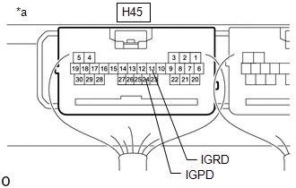
(a) Disconnect the H45 certification ECU (smart key ECU assembly) connector.
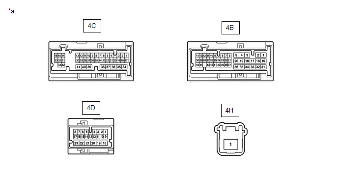
(b) Disconnect the 4B and 4C power distribution box assembly connectors.
(c) Measure the resistance according to the value(s) in the table below.
Standard Resistance:
| Tester Connection | Condition | Specified Condition |
|---|---|---|
| H45-24 (IGPD) - 4C-17 | Always | Below 1 Ω |
| H45-11 (IGRD) - 4B-11 | Always | Below 1 Ω |
| 4B-36 - Body ground | Always | Below 1 Ω |
| H45-24 (IGPD) or 4C-17 - Other terminals and body ground | Always | 10 kΩ or higher |
| H45-11 (IGRD) or 4B-11 - Other terminals and body ground | Always | 10 kΩ or higher |
(d) Connect the H45 certification ECU (smart key ECU assembly) connector.
| NG |
 | REPAIR OR REPLACE HARNESS OR CONNECTOR |
|

| 3. | CHECK CERTIFICATION ECU (SMART KEY ECU ASSEMBLY) |
| (a) Measure the voltage according to the value(s) in the table below. Standard Voltage:
|
|
| NG |
 | REPLACE CERTIFICATION ECU (SMART KEY ECU ASSEMBLY) |
|

| 4. | CHECK HARNESS AND CONNECTOR (POWER DISTRIBUTION BOX ASSEMBLY - POWER SOURCE) |
(a) Disconnect the H45 certification ECU (smart key ECU assembly) connector.
(b) Disconnect the 4D and 4H power distribution box assembly connectors.
(c) Measure the voltage according to the value(s) in the table below.
Standard Voltage:
| Tester Connection | Switch Condition | Specified Condition |
|---|---|---|
| 4H-1 - Body ground | Ignition switch off | 11 to 14 V |
| NG |
 | REPAIR OR REPLACE HARNESS OR CONNECTOR |
|

| 5. | CHECK POWER DISTRIBUTION BOX ASSEMBLY |
(a) Remove the power distribution box assembly.
Click here

(b) Remove the main body ECU (multiplex network body ECU) from the power distribution box assembly.
| *a | Component without harness connected (Power Distribution Box Assembly) | - | - |
(c) Measure the resisitance according to the value(s) in the table below.
Standard Resistance:
| Tester Connection | Condition | Specified Condition |
|---|---|---|
| 4C-17 - 4D-13 | Always | Below 1 Ω |
(d) Connect the auxiliary battery terminal (+) to the 4C-17 terminal.
(e) Connect the auxiliary battery terminal (-) to the 4B-36 terminal.
(f) Measure the resistance according to the value(s) in the table below.
Standard Resistance:
| Tester Connection | Condition | Specified Condition |
|---|---|---|
| 4H-1 - 4C-34 | Auxiliary battery voltage applied between terminals 4C-17 and 4B-36 | Below 1 Ω |
| 4H-1 - 4B-38 | Auxiliary battery voltage applied between terminals 4C-17 and 4B-36 | Below 1 Ω |
(g) Connect the auxiliary battery terminal (+) to the 4B-11 terminal.
(h) Connect the auxiliary battery terminal (-) to the 4B-36 terminal.
(i) Measure the resistance according to the value(s) in the table below.
Standard Resistance:
| Tester Connection | Condition | Specified Condition |
|---|---|---|
| 4H-1 - 4C-34 | Auxiliary battery voltage applied between terminals 4B-11 and 4B-36 | Below 1 Ω |
| 4H-1 - 4B-38 | Auxiliary battery voltage applied between terminals 4B-11 and 4B-36 | Below 1 Ω |
| NG |
 | REPLACE POWER DISTRIBUTION BOX ASSEMBLY |
|

| 6. | CHECK HARNESS AND CONNECTOR (POWER DISTRIBUTION BOX ASSEMBLY - IGP RELAY) |
(a) Disconnect the 4D power distribution box assembly connector.
(b) Remove the IGP relay.
(c) Measure the resistance according to the value(s) in the table below.
Standard Resistance:
| Tester Connection | Condition | Specified Condition |
|---|---|---|
| 4D-13 - No. 1 engine room relay block assembly IGP relay terminal 1 | Always | Below 1 Ω |
| No. 1 engine room relay block assembly IGP relay terminal 2 - Body ground | Always | Below 1 Ω |
| 4D-13 or No. 1 engine room relay block assembly IGP relay terminal 1 - Other terminals and body ground | Always | 10 kΩ or higher |
| NG |
 | REPAIR OR REPLACE HARNESS OR CONNECTOR |
|

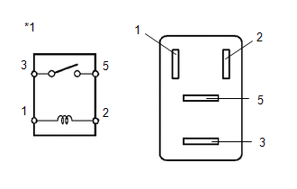
| 7. | INSPECT IGP RELAY |
| (a) Measure the resistance according to the value(s) in the table below. Standard Resistance::
|
|
| OK |
 | REPAIR OR REPLACE HARNESS OR CONNECTOR |
| NG |
 | REPLACE IGP RELAY |
 Power Source Mode does not Change to ON (IG and ACC)
DESCRIPTION When the ignition switch cannot be turned to ACC or ON, interior verification may be abnormal or there may be a malfunction in the ACC relay or IG relay circuit...
 Power Source Mode does not Change to ON (ACC)
DESCRIPTION If the engine switch is pressed with the electrical key transmitter sub-assembly in the cabin, the certification ECU (smart key ECU assembly) receives a signal and changes the power source mode...
Other information:
Toyota Yaris XP210 (2020-2026) Reapir and Service Manual: Steering Angle Sensor Module Component Internal Failure (C052696)
DESCRIPTION The skid control ECU (brake actuator assembly) outputs this DTC when it receives an internal malfunction signal from the steering sensor. DTC No. Detection Item DTC Detection Condition Trouble Area DTC Output from C052696 Steering Angle Sensor Module Component Internal Failure With the +BS terminal voltage 9...
Toyota Yaris XP210 (2020-2026) Reapir and Service Manual: Inspection
INSPECTION PROCEDURE 1. INSPECT OIL PRESSURE AND TEMPERATURE SENSOR (a) Check the oil pressure and temperature sensor output voltage. (1) Apply 5 V between terminals 3 (VC) and 2 (GND). NOTICE: Be careful when connecting the leads as the oil pressure and temperature sensor may be damaged if the leads are connected to the wrong terminals...
Categories
- Manuals Home
- Toyota Yaris Owners Manual
- Toyota Yaris Service Manual
- Removal
- Battery Monitor Module General Electrical Failure (P058A01)
- Key Battery Replacement
- New on site
- Most important about car
Break-In Period
No special break-in is necessary, but a few precautions in the first 600 miles (1,000 km) may add to the performance, economy, and life of the vehicle.
Do not race the engine. Do not maintain one constant speed, either slow or fast, for a long period of time. Do not drive constantly at full-throttle or high engine rpm for extended periods of time. Avoid unnecessary hard stops. Avoid full-throttle starts.