Toyota Yaris: Smart Key System (for Start Function) / Power Source Mode does not Change to ON (ACC)
DESCRIPTION
If the engine switch is pressed with the electrical key transmitter sub-assembly in the cabin, the certification ECU (smart key ECU assembly) receives a signal and changes the power source mode.
Related Data List and Active Test Items| Problem Symptom | Data List and Active Test |
|---|---|
| Power source mode does not change to on (ACC) but does change to on (IG) | Power Source Control
|
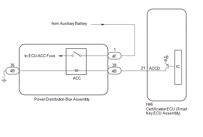
WIRING DIAGRAM
CAUTION / NOTICE / HINT
NOTICE:
- When using the GTS with the ignition switch off, connect the GTS to the DLC3 and turn a courtesy light switch on and off at intervals of 1.5 seconds or less until communication between the GTS and the vehicle begins. Then select the vehicle type under manual mode and enter the following menus: Body Electrical / Smart Key. While using the GTS, periodically turn a courtesy light switch on and off at intervals of 1.5 seconds or less to maintain communication between the GTS and the vehicle.
-
The smart key system (for Start Function) uses the LIN communication system and CAN communication system. Inspect the communication function by following How to Proceed with Troubleshooting. Troubleshoot the smart key system (for Start Function) after confirming that the communication systems are functioning properly.
Click here

- Make sure that no DTCs are output. If any DTCs are output, proceed to Diagnostic Trouble Code Chart.
-
If the smart key system (for Start Function) has been disabled, enable the system before performing troubleshooting.
Click here

- Inspect the fuses for circuits related to this system before performing the following procedure.
-
Before replacing the certification ECU (smart key ECU assembly), refer to Registration.
Click here

- After completing repairs, confirm that the problem does not recur.
- After performing repairs, confirm that no DTCs are output by performing "DTC Output Confirmation Operation."
PROCEDURE
| 1. | CHECK FOR DTC |
(a) Using the GTS, check for certification ECU (smart key ECU assembly) DTCs.
Body Electrical > Power Source Control > Trouble Codes Body Electrical > Smart Key > Trouble Codes| Result | Proceed to |
|---|---|
| DTCs are not output | A |
| Smart key system (for Start Function) DTCs are output | B |
| B |
 | GO TO DIAGNOSTIC TROUBLE CODE CHART |
|

| 2. | CHECK HARNESS AND CONNECTOR (POWER DISTRIBUTION BOX ASSEMBLY - POWER SOURCE) |
(a) Disconnect the 4F power distribution box assembly connector.
(b) Measure the voltage according to the value(s) in the table below.
Standard Voltage:
| Tester Connection | Switch Condition | Specified Condition |
|---|---|---|
| 4F-1 - Body ground | Ignition switch off | 11 to 14 V |
| NG |
 | REPAIR OR REPLACE HARNESS OR CONNECTOR |
|

| 3. | CHECK POWER DISTRIBUTION BOX ASSEMBLY (ACC RELAY) |
(a) Remove the power distribution box assembly.
Click here

(b) Remove the main body ECU (multiplex network body ECU) from the power distribution box assembly.
(c) Connect the auxiliary battery terminal (+) to the 4B-39 terminal.
(d) Connect the auxiliary battery terminal (-) to the 4B-36 terminal.
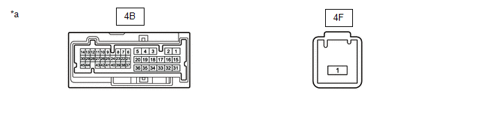
| *a | Component without harness connected (Power Distribution Box Assembly) | - | - |
(e) Measure the resistance according to the value(s) in the table below.
Standard Resistance:
| Tester Connection | Condition | Specified Condition |
|---|---|---|
| 4F-1 - 4B-12 | Auxiliary battery voltage applied between terminals 4B-39 and 4B-36 | Below 1 Ω |
| OK |
 | REPAIR OR REPLACE HARNESS OR CONNECTOR |
| NG |
 | REPLACE POWER DISTRIBUTION BOX ASSEMBLY |
 Power Source Mode does not Change to ON (IG)
DESCRIPTION If the engine switch is pressed with the electrical key transmitter sub-assembly in the cabin, the certification ECU (smart key ECU assembly) receives a signal and changes the power source mode...
 New Key cannot be Registered
DESCRIPTION If a new electrical key transmitter sub-assembly could not be registered, wave interference or a malfunction of the certification ECU (smart key ECU assembly), ID code box (immobiliser code ECU), electrical key transmitter sub-assembly, steering lock ECU (steering lock actuator or upper bracket assembly), smart door control receiver assembly is suspected...
Other information:
Toyota Yaris XP210 (2020-2026) Reapir and Service Manual: Problem Symptoms Table
PROBLEM SYMPTOMS TABLE HINT: Use the table below to help determine the cause of problem symptoms. If multiple suspected areas are listed, the potential causes of the symptoms are listed in order of probability in the "Suspected Area" column of the table...
Toyota Yaris XP210 (2020-2026) Owner's Manual: Seat Precautions
When returning a rear seat to its original position, place the seat belt in its normal position. Verify that the seat belt pulls out and retracts. WARNING Make sure the adjustable components of a seat are locked in place Adjustable seats and seatbacks that are not securely locked are dangerous...
Categories
- Manuals Home
- Toyota Yaris Owners Manual
- Toyota Yaris Service Manual
- Diagnostic Trouble Code Chart
- Headlights
- Adjustment
- New on site
- Most important about car
Supplemental Restraint System (SRS) Precautions
The front and side supplemental restraint systems (SRS) include different types of air bags. Please verify the different types of air bags which are equipped on your vehicle by locating the “SRS AIRBAG” location indicators. These indicators are visible in the area where the air bags are installed.
The air bags are installed in the following locations:
The steering wheel hub (driver air bag) The front passenger dashboard (front passenger air bag) The outboard sides of the front seatbacks (side air bags) The front and rear window pillars, and the roof edge along both sides (curtain air bags)