Toyota Yaris: Side Airbag Sensor (for Rear Pillar) / Removal
REMOVAL
CAUTION / NOTICE / HINT
The necessary procedures (adjustment, calibration, initialization or registration) that must be performed after parts are removed, installed or replaced during the No. 1 side airbag sensor removal/installation are shown below.
HINT:
-
When the cable is disconnected / reconnected to the auxiliary battery terminal, systems temporarily stop operating. However, each system has a function that completes learning the first time the system is used.
-
Learning completes when vehicle is driven
Effect/Inoperative Function When Necessary Procedures are not Performed
Necessary Procedures
Link
Lane tracing assist system
Drive the vehicle straight ahead at 35 km/h (22 mph) or more for 5 seconds or more.

Pre-collision system
Stop and start system
Drive the vehicle until stop and start control is permitted (approximately 5 to 60 minutes)

-
Learning completes when vehicle is operated normally
Effect/Inoperative Function When Necessary Procedures are not Performed
Necessary Procedures
Link
Power door lock control system
- Back door opener
Perform door unlock operation with door control switch or electrical key transmitter sub-assembly switch.

Air conditioning system
After the ignition switch is turned to ON, the servo motor standard position is recognized.
-
-
Learning completes when vehicle is driven
- Use the same procedure for the RH and LH sides.
- The procedure listed below is for the LH side.
PROCEDURE
1. PRECAUTION
CAUTION:
Be sure to read precaution thoroughly before servicing.
Click here

NOTICE:
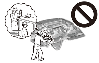
After turning the ignition switch off, waiting time may be required before disconnecting the cable from the negative (-) auxiliary battery terminal.
Click here

2. DISCONNECT CABLE FROM NEGATIVE AUXILIARY BATTERY TERMINAL
Click here

CAUTION:
- Wait at least 90 seconds after disconnecting the cable from the negative (-) auxiliary battery terminal to disable the SRS system.
- If the airbag deploys for any reason, it may cause a serious accident.
3. REMOVE REAR SEATBACK ASSEMBLY
Click here

4. REMOVE BENCH TYPE REAR SEAT CUSHION ASSEMBLY
Click here

5. REMOVE REAR SEAT CUSHION LOCK HOOK
Click here

6. REMOVE FRONT DOOR SCUFF PLATE
Click here

7. REMOVE LAP BELT OUTER ANCHOR COVER
Click here

8. DISCONNECT FRONT SEAT OUTER BELT ASSEMBLY
Click here

9. REMOVE QUARTER TRIM PANEL ASSEMBLY
Click here

10. DISCONNECT FRONT SEAT OUTER BELT ASSEMBLY
| (a) Using a screwdriver with its tip wrapped in protective tape, pull out the locking button to release the lock to disconnect the pretensioner connector as shown in the illustration. |
|
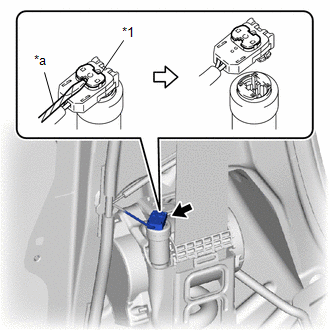
| (b) Remove the 2 bolts. |
|

(c) Disengage the guides to disconnect the front seat outer belt assembly.
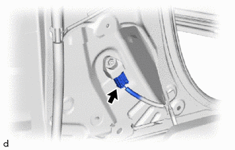
11. REMOVE NO. 1 SIDE AIRBAG SENSOR
(a) Check that the ignition switch is off.
(b) Check that the cable is disconnected from the negative (-) auxiliary battery terminal.
CAUTION:
- Wait at least 90 seconds after disconnecting the cable from the negative (-) auxiliary battery terminal to disable the SRS system.
- If the airbag deploys for any reason, it may cause a serious accident.
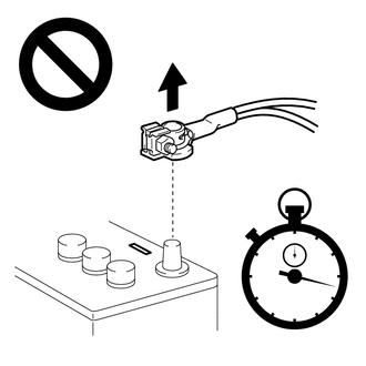
| (c) Disconnect the airbag connector. NOTICE: When disconnecting any airbag connector, take care not to damage the airbag wire harness. HINT: Refer to How to Connect or Disconnect Airbag Connector: Click here
|
|

| (d) Remove the nut. NOTICE:
|
|
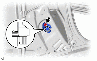
(e) Disengage the claw to remove the No. 1 side airbag sensor.
 Components
COMPONENTS ILLUSTRATION
*1 REAR SEATBACK ASSEMBLY *2 BENCH TYPE REAR SEAT CUSHION ASSEMBLY *3 REAR SEAT CUSHION LOCK HOOK - -
Tightening torque for "Major areas involving basic vehicle performance such as moving/turning/stopping" : N*m (kgf*cm, ft...
 Installation
INSTALLATION CAUTION / NOTICE / HINT HINT:
Use the same procedure for the RH and LH sides.
The procedure listed below is for the LH side.
PROCEDURE 1...
Other information:
Toyota Yaris XP210 (2020-2026) Owner's Manual: Tiedown Hook-Rear
The hook positioned under the rear bumper on the right side is for tying down the vehicle during transport, and it cannot be used for towing other vehicles. It can be used as a towing hook only when the vehicle must be towed by another vehicle in an emergency case such as when the vehicle is stuck in snow, however, it may damage the bumper...
Toyota Yaris XP210 (2020-2026) Reapir and Service Manual: Front Recognition Camera Heater Malfunction (C1AAE00)
DESCRIPTION The forward recognition camera controls the flow of current to the forward recognition with heater hood sub-assembly. If the forward recognition camera detects a malfunction in the forward recognition with heater hood sub-assembly circuit, it will store this DTC...
Categories
- Manuals Home
- Toyota Yaris Owners Manual
- Toyota Yaris Service Manual
- How to use USB mode
- Removal
- G16e-gts (engine Mechanical)
- New on site
- Most important about car
Keys

To use the auxiliary key, press the knob and pull out the auxiliary key from the smart key.
