Toyota Yaris: Active Torque Split Awd System / Terminals Of Ecu
TERMINALS OF ECU
CHECK AWD ECU ASSEMBLY

(a) Measure the voltage and resistance of the connector.
| Terminal No. (Symbol) | Terminal Description | Condition | Specified Condition |
|---|---|---|---|
| O119-1 (GND) - Body ground | Ground | Always | Below 1 Ω |
| O119-2 (BSLC) - O119-1 (GND) | AWD ECU assembly power supply | Always | 11 to 14 V |
| O119-13 (T1H) - O119-1 (GND) | Temperature sensor (+) input | Ignition switch ON | 0.5 to 4.5 V |
| O119-21 (T1L) - O119-1 (GND) | Temperature sensor (-) input | Ignition switch ON | 0.5 to 4.5 V |
| O119-24 (IG1) - O119-1 (GND) | AWD ECU assembly power supply input | Ignition switch ON | 11 to 14 V |
| O120-3 (SLC-) - O119-1 (GND) | AWD linear solenoid (transmission coupling assembly) (-) output | Ignition switch ON | Below 0.5 V |
| O120-4 (SLC+) - O119-1 (GND) | AWD linear solenoid (transmission coupling assembly) (+) output | Ignition switch ON | Below 0.5 V |
| O120-17 (CANH) - O120-26 (CANL) | CAN communication line | Ignition switch off | 54 to 69 Ω |
CHECK ECM
HINT:
The standard voltage, resistance and waveform between each pair of the ECM terminals is shown in the table below.
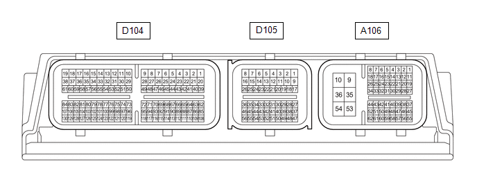
The appropriate conditions for checking each pair of the terminals are also indicated. The result of checks should be compared with the standard voltage, resistance and waveform for each pair of the terminals as displayed in the Specified Condition column. The illustration above can be used as a reference to identify the ECM terminal locations.
(a) Measure the voltage and resistance of the connector.
| Terminal No. (Symbol) | Terminal Description | Condition | Specified Condition |
|---|---|---|---|
| A106-10 (E1) - Body ground | Ground | Always | Below 1 Ω |
| A106-31 (PWMS) - A106-10 (E1) | SPORT mode switch input |
| 4.5 to 5.5 V |
| 11 to 14 V | ||
| A106-24 (TRMS) - A106-10 (E1) | TRACK mode switch input |
| 4.5 to 5.5 V |
| 11 to 14 V | ||
| A106-51 (SPCN) - A106-10 (E1) | NORMAL mode switch input |
| 4.5 to 5.5 V |
| 11 to 14 V |
 Dtc Check / Clear
DTC CHECK / CLEAR DTC CHECK (a) Check for DTC(s). Chassis > Four Wheel Drive > Trouble Codes (b) Check the details of the DTCs. NOTICE:
Make sure to clear the DTCs after repair...
 Freeze Frame Data
FREEZE FRAME DATA FREEZE FRAME DATA (a) When a DTC is stored, the AWD ECU assembly stores the current vehicle state as Freeze Frame Data. HINT: Freeze Frame Data at the time a DTC is stored:
When the AWD ECU assembly stores data at the time a DTC is stored, no updates will be performed until the data is cleared...
Other information:
Toyota Yaris XP210 (2020-2026) Reapir and Service Manual: Removal
REMOVAL CAUTION / NOTICE / HINT HINT: When the cable is disconnected/reconnected to the auxiliary battery terminal, systems temporarily stop operating. However, each system has a function that completes learning the first time the system is used. Learning completes when vehicle is driven Effect/Inoperative Function When Necessary Procedures are not Performed Necessary Procedures Link Lane tracing assist system Drive the vehicle straight ahead at 35 km/h (22 mph) or more for 5 second or more...
Toyota Yaris XP210 (2020-2026) Reapir and Service Manual: Removal
REMOVAL CAUTION / NOTICE / HINT HINT: Use the same procedure for the RH side and LH side. The following procedure is for the LH side. PROCEDURE 1. REMOVE FRONT WHEEL Click here 2. DRAIN BRAKE FLUID NOTICE: If brake fluid leaks onto any painted surface, immediately wash it off...
Categories
- Manuals Home
- Toyota Yaris Owners Manual
- Toyota Yaris Service Manual
- Engine & Hybrid System
- How to use USB mode
- How to connect USB port/Auxiliary jack
- New on site
- Most important about car
Turning the Engine Off
Stop the vehicle completely. Manual transaxle: Shift into neutral and set the parking brake.Automatic transaxle: Shift the selector lever to the P position and set the parking brake.
Press the push button start to turn off the engine. The ignition position is off.