Toyota Yaris: Smart Key System (for Start Function) / Engine does not Start
DESCRIPTION
When the electrical key transmitter sub-assembly is in the cabin and the engine switch is pressed, the certification ECU (smart key ECU assembly) receives a signal and changes the power source mode. Additionally, when the clutch pedal is depressed, the engine can be started by pressing the engine switch.
Related Data List and Active Test Items| Problem Symptom | Data List and Active Test |
|---|---|
| Engine does not start | Power Source Control
Smart Key
|
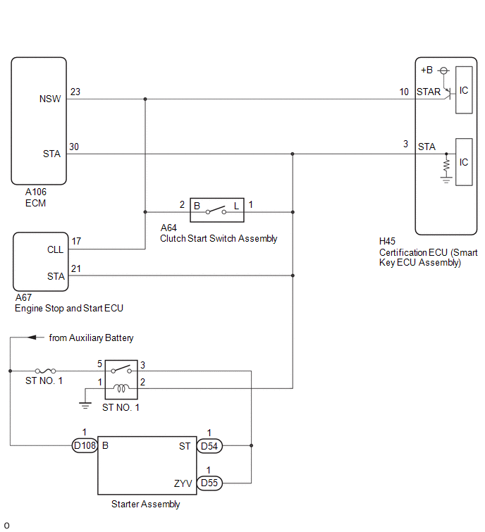
WIRING DIAGRAM
CAUTION / NOTICE / HINT
NOTICE:
- When using the GTS with the ignition switch off, connect the GTS to the DLC3 and turn a courtesy light switch on and off at intervals of 1.5 seconds or less until communication between the GTS and the vehicle begins. Then select the vehicle type under manual mode and enter the following menus: Body Electrical / Smart Key. While using the GTS, periodically turn a courtesy light switch on and off at intervals of 1.5 seconds or less to maintain communication between the GTS and the vehicle.
-
If the smart key system (for Start Function) has been disabled, enable the system before performing troubleshooting.
Click here

- Inspect the fuses for circuits related to this system before performing the following procedure.
-
Before replacing the certification ECU (smart key ECU assembly) or an electrical key transmitter sub-assembly, refer to Registration.
Click here

- After completing repairs, confirm that the problem does not recur.
- After performing repairs, confirm that no DTCs are output by performing "DTC Output Confirmation Operation."
PROCEDURE
| 1. | CHECK ENGINE SWITCH CONDITION |
(a) Get into the vehicle while carrying an electrical key transmitter sub-assembly.
(b) With the clutch pedal released, check that pressing the engine switch causes the power source mode to change.
| Result | Proceed to |
|---|---|
| Power source mode changes : Off → ACC → ON → off | A |
| Power source mode does not change to ACC or ON | B |
| Power source mode changes to ON but not to ACC | C |
| Power source mode changes to ACC but not to ON | D |
| B |
 | GO TO OTHER PROBLEM (Power Source Mode does not Change to ON (IG and ACC)) |
| C |
 | GO TO OTHER PROBLEM (Power Source Mode does not Change to ON (ACC)) |
| D |
 | GO TO OTHER PROBLEM (Power Source Mode does not Change to ON (IG)) |
|

| 2. | READ VALUE USING GTS (NEUTRAL SW/ CLUTCH SW) |
(a) Read the Data List according to the display on the GTS.
Body Electrical > Power Source Control > Data List| Tester Display | Measurement Item | Range | Normal Condition | Diagnostic Note |
|---|---|---|---|---|
| Neutral Switch / Clutch Switch | State of clutch pedal | OFF or ON | OFF: Clutch pedal released ON: Clutch pedal depressed |
|
| Tester Display |
|---|
| Neutral Switch / Clutch Switch |
OK:
The GTS display changes correctly in response to the clutch pedal operation.
| NG |
 | GO TO STEP 12 |
|

| 3. | READ VALUE USING GTS (POWER SUPPLY CONDITION) |
(a) Read the Data List according to the display on the GTS.
Body Electrical > Power Source Control > Data List| Tester Display | Measurement Item | Range | Normal Condition | Diagnostic Note |
|---|---|---|---|---|
| Power Supply Condition | Power supply state | OFF, ACC ON, IGR ON, IGP ON or Starter ON | OFF: Ignition switch off ACC ON: Ignition switch ACC IGR ON: Ignition switch ON IGP ON: Ignition switch ON Starter ON: Sending engine start request signal | - |
| Tester Display |
|---|
| Power Supply Condition |
NOTICE:
Check that the key indicator display is displayed on the multi-information display in the combination meter assembly, and then press the engine switch.
OK:
The GTS display changes correctly in response to the engine switch operation.
| NG |
 | GO TO STEP 10 |
|

| 4. | CHECK HARNESS AND CONNECTOR (CERTIFICATION ECU (SMART KEY ECU ASSEMBLY) - ST NO. 1 RELAY) |
| (a) Measure the voltage according to the value(s) in the table below. Standard Voltage:
HINT: *: While the engine is cranking, the auxiliary battery voltage may drop to approximately 6 V. |
|

| NG |
 | GO TO STEP 9 |
|

| 5. | CHECK HARNESS AND CONNECTOR (ST NO. 1 RELAY - AUXILIARY BATTERY AND GROUND) |
| (a) Measure the resistance according to the value(s) in the table below. Standard Resistance:
|
|
(b) Measure the voltage according to the value(s) in the table below.
Standard Voltage:
| Tester Connection | Condition | Specified Condition |
|---|---|---|
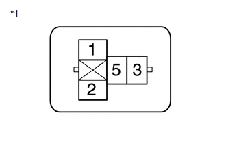
| No. 1 engine room relay block assembly ST NO. 1 relay terminal 5 - Body ground | Always | 11 to 14 V |
| NG |
 | REPAIR OR REPLACE HARNESS OR CONNECTOR |
|

| 6. | INSPECT ST NO. 1 RELAY |
Click here

| NG |
 | REPLACE ST NO. 1 RELAY |
|

| 7. | CHECK HARNESS AND CONNECTOR (STARTER ASSEMBLY - ST NO. 1 RELAY) |
(a) Disconnect the D54 and D55 starter assembly connector.
(b) Measure the resistance according to the value(s) in the table below.
Standard Resistance:
| Tester Connection | Condition | Specified Condition |
|---|---|---|
| No. 1 engine room relay block assembly ST NO. 1 relay terminal 3 - D54-1 | Always | Below 1 Ω |
| No. 1 engine room relay block assembly ST NO. 1 relay terminal 3 - D55-1 | Always | Below 1 Ω |
| No. 1 engine room relay block assembly ST NO. 1 relay terminal 3 or D54-1 - Other terminals and body ground | Always | 10 kΩ or higher |
| No. 1 engine room relay block assembly ST NO. 1 relay terminal 3 or D55-1 - Other terminals and body ground | Always | 10 kΩ or higher |
| NG |
 | REPAIR OR REPLACE HARNESS OR CONNECTOR |
|

| 8. | CHECK HARNESS AND CONNECTOR (STARTER ASSEMBLY - AUXILIARY BATTERY) |
(a) Disconnect the D108 starter assembly connector.
(b) Measure the voltage according to the value(s) in the table below.
Standard Voltage:
| Tester Connection | Condition | Specified Condition |
|---|---|---|
| D108-1 (B) - Body ground | Always | 11 to 14 V |
| OK |
 | REPLACE STARTER ASSEMBLY |
| NG |
 | REPAIR OR REPLACE HARNESS OR CONNECTOR |
| 9. | CHECK HARNESS AND CONNECTOR (CLUTCH START SWITCH ASSEMBLY - ST NO. 1 RELAY) |
(a) Disconnect the A64 clutch start switch assembly connector.
(b) Disconnect the A67 engine stop and start ECU connector.
(c) Measure the resistance according to the value(s) in the table below.
Standard Resistance:
| Tester Connection | Condition | Specified Condition |
|---|---|---|
| A64-1 (L) - 2 (ST NO. 1 relay) | Always | Below 1 Ω |
| A64-1 (L) or 2 (ST NO. 1 relay) - Other terminals and body ground | Always | 10 kΩ or higher |
| OK |
 | REPLACE CERTIFICATION ECU (SMART KEY ECU ASSEMBLY) |
| NG |
 | REPAIR OR REPLACE HARNESS OR CONNECTOR |
| 10. | CHECK STEERING LOCK FUNCTION |
(a) Check that the steering unlocks when the ignition switch is turned to ACC.
OK:
The steering unlocks.
| NG |
 | GO TO OTHER PROBLEM (Unable to Unlock Steering Wheel (Engine cannot Start)) |
|

| 11. | CHECK SECURITY INDICATOR LIGHT (IMMOBILISER FUNCTION UNSET) |
(a) Get into the vehicle while carrying an electrical key transmitter sub-assembly.
(b) Press the engine switch with the clutch pedal released and check that the security indicator light changes from blinking to off at the same time that the power source mode changes to ACC.
OK:
The security indicator light changes from blinking to off at the same time that the power source mode changes to ACC.
HINT:
The immobiliser function can be determined to be operating correctly if the security indicator light changes from blinking to off at the same time that the power source mode changes to ACC.
| OK |
 | REPLACE CERTIFICATION ECU (SMART KEY ECU ASSEMBLY) |
| NG |
 | GO TO OTHER PROBLEM (Immobiliser System does not Operate Properly) |
| 12. | READ VALUE USING GTS (NEUTRAL SW/ CLUTCH SW) |
(a) Disconnect the A106 ECM connector.
(b) Read the Data List according to the display on the GTS.
Body Electrical > Power Source Control > Data List| Tester Display | Measurement Item | Range | Normal Condition | Diagnostic Note |
|---|---|---|---|---|
| Neutral Switch / Clutch Switch | State of clutch pedal | OFF or ON | OFF: Clutch pedal released ON: Clutch pedal depressed |
|
| Tester Display |
|---|
| Neutral Switch / Clutch Switch |
OK:
The GTS display changes correctly in response to the clutch pedal operation.
| OK |
 | REPLACE ECM |
|

| 13. | READ VALUE USING GTS (NEUTRAL SW/ CLUTCH SW) |
(a) Disconnect the A67 engine stop and start ECU connector.
(b) Read the Data List according to the display on the GTS.
Body Electrical > Power Source Control > Data List| Tester Display | Measurement Item | Range | Normal Condition | Diagnostic Note |
|---|---|---|---|---|
| Neutral Switch / Clutch Switch | State of clutch pedal | OFF or ON | OFF: Clutch pedal released ON: Clutch pedal depressed |
|
| Tester Display |
|---|
| Neutral Switch / Clutch Switch |
OK:
The GTS display changes correctly in response to the clutch pedal operation.
| OK |
 | REPLACE ENGINE STOP AND START ECU |
|

| 14. | INSPECT CLUTCH START SWITCH ASSEMBLY |
Click here

| NG |
 | REPLACE CLUTCH START SWITCH ASSEMBLY |
|

| 15. | CHECK HARNESS AND CONNECTOR (CERTIFICATION ECU (SMART KEY ECU ASSEMBLY) - CLUTCH START SWITCH ASSEMBLY) |
(a) Disconnect the H45 certification ECU (smart key ECU assembly) connector.
(b) Disconnect the A64 clutch start switch assembly connector.
(c) Remove the ST NO. 1 relay.
(d) Measure the resistance according to the value(s) in the table below.
Standard Resistance:
| Tester Connection | Condition | Specified Condition |
|---|---|---|
| H45-3 (STA) - A64-1 (L) | Always | Below 1 Ω |
| H45-3 (STA) - A67-21 (STA) | Always | Below 1 Ω |
| H45-10 (STAR) - A106-23 (NSW) | Always | Below 1 Ω |
| H45-10 (STAR) - A64-2 (B) | Always | Below 1 Ω |
| H45-10 (STAR) - A67-17 (CLL) | Always | Below 1 Ω |
| H45-3 (STA) or A64-1 (L) - Other terminals and body ground | Always | 10 kΩ or higher |
| H45-10 (STAR) or A106-23 (NSW) - Other terminals and body ground | Always | 10 kΩ or higher |
| H45-10 (STAR) or A64-2 (B) - Other terminals and body ground | Always | 10 kΩ or higher |
| NG |
 | REPAIR OR REPLACE HARNESS OR CONNECTOR |
|

| 16. | CHECK CERTIFICATION ECU (SMART KEY ECU ASSEMBLY) |
(a) Connect the H45 certification ECU (smart key ECU assembly) connector.
(b) Measure the voltage according to the value(s) in the table below.
Standard Voltage:
| Tester Connection | Condition | Specified Condition |
|---|---|---|
| H45-10 (STAR) - Body ground | Engine switch pressed and held with clutch pedal depressed (starter on) → Approximately 1 second after engine switch released (starter off) | 6 V or higher* → 1.0 V or less |
HINT:
*: While the engine is cranking, the auxiliary battery voltage may drop to approximately 6 V.
| NG |
 | REPLACE CERTIFICATION ECU (SMART KEY ECU ASSEMBLY) |
|

| 17. | INSPECT ST NO. 1 RELAY |
Click here

| OK |
 | REPLACE CERTIFICATION ECU (SMART KEY ECU ASSEMBLY) |
| NG |
 | REPLACE ST NO. 1 RELAY |
 Lost Communication with ECM/PCM "A" Missing Message (U010087,U012987,U014087,U015587,U110387,U111787)
DESCRIPTION These DTCs are stored when there is a CAN communication malfunction between the certification ECU (smart key ECU assembly) and ECM, main body ECU (multiplex network body ECU) or combination meter assembly...
 Power Source Mode does not Change to ON (IG and ACC)
DESCRIPTION When the ignition switch cannot be turned to ACC or ON, interior verification may be abnormal or there may be a malfunction in the ACC relay or IG relay circuit...
Other information:
Toyota Yaris XP210 (2020-2026) Reapir and Service Manual: Installation
INSTALLATION CAUTION / NOTICE / HINT NOTICE: Work indoors with less dust and wind. Install the roof outside cover in an environment where the temperature is 20 to 30°C (68 to 86°F). Do not leave dirt such as old adhesive, bumps, dust and oil on the adhesive surface...
Toyota Yaris XP210 (2020-2026) Reapir and Service Manual: Components
COMPONENTS ILLUSTRATION *1 FRONT FLOOR COVER LH *2 FRONT FLOOR COVER RH *3 FRONT NO. 1 FLOOR HEAT INSULATOR SUB-ASSEMBLY - - N*m (kgf*cm, ft.*lbf): Specified torque - - ILLUSTRATION *1 PROPELLER SHAFT WITH CENTER BEARING ASSEMBLY *2 CENTER NO...
Categories
- Manuals Home
- Toyota Yaris Owners Manual
- Toyota Yaris Service Manual
- Fuse Panel Description
- G16e-gts (engine Mechanical)
- Power Integration No.1 System Missing Message (B235287,B235587,B235787-B235987)
- New on site
- Most important about car
Fuel-Filler Lid and Cap
WARNING
When removing the fuel-filler cap, loosen the cap slightly and wait for any hissing to stop, then remove it
Fuel spray is dangerous. Fuel can burn skin and eyes and cause illness if ingested. Fuel spray is released when there is pressure in the fuel tank and the fuel-filler cap is removed too quickly.