Toyota Yaris: Rear Stabilizer Bar / Inspection
INSPECTION
PROCEDURE
1. INSPECT REAR STABILIZER LINK ASSEMBLY
(a) Inspect the turning torque of the ball joint.
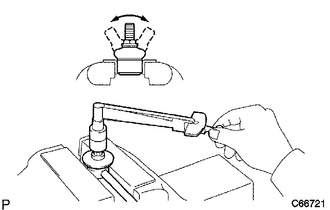
(1) Secure the rear stabilizer link assembly in a vise using aluminum plates.
NOTICE:
Do not overtighten the vise.
(2) Install the nut to the rear stabilizer link assembly stud.
(3) Move the stud back and forth several times. Using a torque wrench, turn the stud continuously at a rate of 3 to 5 seconds per turn and take the torque reading on the 5th turn.
Standard Turning Torque:
0.05 to 1.96 N*m (0.6 to 19 kgf*cm, 0.5 to 17 in.*lbf)
HINT:
If the turning torque is not within the specified range, replace the rear stabilizer link assembly with a new one.
(4) Turn the stud to check that the stud does not catch and there is no play
HINT:
If the stud catches or there is play while turning, replace the rear stabilizer link assembly with a new one.
(b) Inspect the dust cover.
(1) Check that the dust cover is not cracked and that there is no grease on it.
HINT:
If the dust cover is cracked or there is grease on it, replace the rear stabilizer link assembly with a new one.
 Removal
REMOVAL PROCEDURE 1. REMOVE REAR WHEEL Click here
2. REMOVE REAR STABILIZER LINK ASSEMBLY LH (a) Remove the cap.
(b) Loosen the nut (A) of the rear stabilizer link assembly LH...
 Installation
INSTALLATION PROCEDURE 1. INSTALL REAR STABILIZER BAR (a) Install the rear stabilizer bar to the rear suspension member sub-assembly with the 4 bolts...
Other information:
Toyota Yaris XP210 (2020-2026) Reapir and Service Manual: Door Control Transmitter
ComponentsCOMPONENTS ILLUSTRATION *1 MECHANICAL KEY *2 TRANSMITTER BATTERY *3 TRANSMITTER HOUSING CASE *4 TRANSMITTER HOUSING COVER InspectionINSPECTION PROCEDURE 1. INSPECT ELECTRICAL KEY TRANSMITTER SUB-ASSEMBLY (a) Inspect the operation of the electrical key transmitter sub-assembly...
Toyota Yaris XP210 (2020-2026) Reapir and Service Manual: Removal
REMOVAL CAUTION / NOTICE / HINT The necessary procedures (adjustment, calibration, initialization, or registration) that must be performed after parts are removed and installed, or replaced during cylinder head gasket removal/installation are shown below...
Categories
- Manuals Home
- Toyota Yaris Owners Manual
- Toyota Yaris Service Manual
- Immobilizer System
- Adjustment
- How to use USB mode
- New on site
- Most important about car
Break-In Period
No special break-in is necessary, but a few precautions in the first 600 miles (1,000 km) may add to the performance, economy, and life of the vehicle.
Do not race the engine. Do not maintain one constant speed, either slow or fast, for a long period of time. Do not drive constantly at full-throttle or high engine rpm for extended periods of time. Avoid unnecessary hard stops. Avoid full-throttle starts.