
Toyota Yaris: Exhaust Pipe / Components
COMPONENTS
ILLUSTRATION
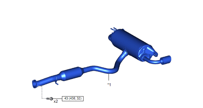
| *1 | TAIL EXHAUST PIPE ASSEMBLY | - | - |
 | N*m (kgf*cm, ft.*lbf): Specified torque | - | - |
ILLUSTRATION
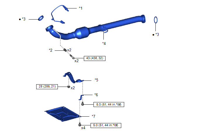
| *1 | NO. 2 AIR FUEL RATIO SENSOR | *2 | COMPRESSION SPRING |
| *3 | EXHAUST PIPE GASKET | *4 | FRONT EXHAUST PIPE ASSEMBLY |
| *5 | CENTER NO. 4 ENGINE UNDER COVER | *6 | FRONT FLOOR CENTER BRACE |
| *7 | CENTER NO. 1 FLOOR BRACE | - | - |
 | N*m (kgf*cm, ft.*lbf): Specified torque | ● | Non-reusable part |
 Exhaust Pipe
..
 Removal
REMOVAL CAUTION / NOTICE / HINT The necessary procedures (adjustment, calibration, initialization or registration) that must be performed after parts are removed and installed, or replaced during front exhaust pipe assembly and tail exhaust pipe assembly removal/installation are shown below...
Other information:
Toyota Yaris XP210 (2020-2026) Owner's Manual: Tiedown Hook-Rear
The hook positioned under the rear bumper on the right side is for tying down the vehicle during transport, and it cannot be used for towing other vehicles. It can be used as a towing hook only when the vehicle must be towed by another vehicle in an emergency case such as when the vehicle is stuck in snow, however, it may damage the bumper...
Toyota Yaris XP210 (2020-2026) Reapir and Service Manual: Throttle/Pedal Position Sensor "A" Minimum Stop Performance (P210900)
DESCRIPTION The idle speed is controlled by the Electronic Throttle Control System (ETCS). The ETCS is comprised of a throttle actuator, which operates the throttle valve, and a throttle position sensor, which detects the opening amount of the throttle valve...
Categories
- Manuals Home
- Toyota Yaris Owners Manual
- Toyota Yaris Service Manual
- Immobilizer System
- To Set Speed
- Fuel Gauge
- New on site
- Most important about car
Front Seat Belt Pretensioners
The front seat belt pretensioners are designed to deploy in moderate or severe frontal, near frontal collisions.
In addition, the pretensioners operate when a side collision or a rollover accident is detected. The pretensioners operate differently depending on what types of air bags are equipped. For more details about the seat belt pretensioner operation, refer to the SRS Air Bag Deployment Criteria.
