Toyota Yaris: Rear Stabilizer Bar / Removal
REMOVAL
PROCEDURE
1. REMOVE REAR WHEEL
Click here

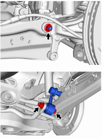
2. REMOVE REAR STABILIZER LINK ASSEMBLY LH
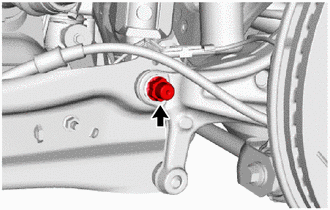
| (a) Remove the cap. |
|
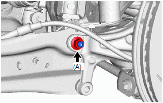
| (b) Loosen the nut (A) of the rear stabilizer link assembly LH. HINT: If the ball joint turns together with the nut, use a 6 mm hexagon socket wrench to hold the stud bolt. |
|
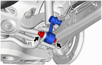
| (c) Loosen the nut (B) of the rear stabilizer link assembly LH. NOTICE: Loosen the nut with the bolt secured. |
|
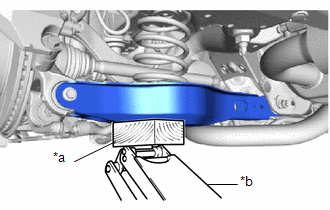
| (d) Using a jack and a wooden block, support the rear No. 2 suspension arm assembly. NOTICE:
|
|
| (e) Remove the bolt, 2 nuts and rear stabilizer link assembly LH. |
|
3. REMOVE REAR STABILIZER LINK ASSEMBLY RH
HINT:
Perform the same procedure as for the LH side.
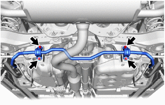
4. REMOVE REAR STABILIZER BAR
| (a) Remove the 4 bolts and rear stabilizer bar from the rear suspension member sub-assembly. |
|
 Components
COMPONENTS ILLUSTRATION
*1 REAR NO. 1 STABILIZER BAR BRACKET *2 REAR STABILIZER BAR *3 REAR STABILIZER BUSHING *4 REAR STABILIZER LINK ASSEMBLY LH *5 REAR STABILIZER LINK ASSEMBLY RH *6 CAP
Tightening torque for "Major areas involving basic vehicle performance such as moving/turning/stopping" : N*m (kgf*cm, ft...
 Inspection
INSPECTION PROCEDURE 1. INSPECT REAR STABILIZER LINK ASSEMBLY
(a) Inspect the turning torque of the ball joint. (1) Secure the rear stabilizer link assembly in a vise using aluminum plates...
Other information:
Toyota Yaris XP210 (2020-2026) Reapir and Service Manual: Steering Angle Sensor Module Signal Stuck In Range (C05262A)
DESCRIPTION The skid control ECU (brake actuator assembly) receives signals from the steering sensor via CAN communication. HINT: When a malfunction occurs in the communication line to the steering sensor, U012687 is output. If a DTC related to the CAN communication line is output, first troubleshoot the CAN communication line...
Toyota Yaris XP210 (2020-2026) Reapir and Service Manual: Freeze Frame Data
FREEZE FRAME DATA DESCRIPTION (a) Whenever a front radar sensor system DTC is stored, the millimeter wave radar sensor assembly stores the current vehicle state as Freeze Frame Data. CHECK FREEZE FRAME DATA (a) According to the display on the GTS, select a DTC with freeze frame data...
Categories
- Manuals Home
- Toyota Yaris Owners Manual
- Toyota Yaris Service Manual
- Engine & Hybrid System
- To Set Speed
- Opening and Closing the Liftgate/Trunk Lid
- New on site
- Most important about car
Fuel Gauge
The fuel gauge shows approximately how much fuel is remaining in the tank when the ignition is switched ON. We recommend keeping the tank over 1/4 full.
