Toyota Yaris: Rear Stabilizer Bar / Installation
INSTALLATION
PROCEDURE
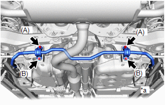
1. INSTALL REAR STABILIZER BAR
| (a) Install the rear stabilizer bar to the rear suspension member sub-assembly with the 4 bolts. Torque: 78 N·m {795 kgf·cm, 58 ft·lbf} NOTICE:
|
|
2. STABILIZE SUSPENSION
Click here

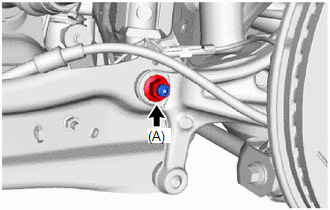
3. INSTALL REAR STABILIZER LINK ASSEMBLY LH
| (a) Install the rear stabilizer link assembly LH with the nut (A). Torque: 75 N·m {765 kgf·cm, 55 ft·lbf} HINT: If the ball joint turns together with the nut, use a 6 mm hexagon socket wrench to hold the stud bolt. |
|
| (b) Install the rear stabilizer link assembly LH with the bolt and nut (B). Torque: 75 N·m {765 kgf·cm, 55 ft·lbf} NOTICE: Tighten the nut with the bolt secured. |
|
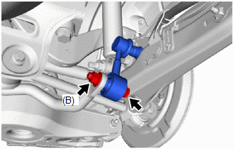
(c) Install the cap.
4. INSTALL REAR STABILIZER LINK ASSEMBLY RH
HINT:
Perform the same procedure as for the LH side.
5. INSTALL REAR WHEEL
Click here

 Inspection
INSPECTION PROCEDURE 1. INSPECT REAR STABILIZER LINK ASSEMBLY
(a) Inspect the turning torque of the ball joint. (1) Secure the rear stabilizer link assembly in a vise using aluminum plates...

Other information:
Toyota Yaris XP210 (2020-2026) Reapir and Service Manual: Excessive Brake Pedal Travel (No Fluid Leaks and No Air in System)
CAUTION / NOTICE / HINT NOTICE: After replacing the skid control ECU (brake actuator assembly), perform "Calibration". Click here PROCEDURE 1. PRE-INSPECTION (a) Brake pedal inspection (1) Perform a visual inspection and operate the brake pedal to check for any malfunctions...
Toyota Yaris XP210 (2020-2026) Reapir and Service Manual: Communication Error from ECM to VSC Invalid Serial Data Received (P163181)
DESCRIPTION The skid control ECU (brake actuator assembly) sends signals such as brake request signals to the ECM. When the ECM detects logic error signals sent from the skid control ECU (brake actuator assembly) for a certain period of time, DTC P163181 is stored...
Categories
- Manuals Home
- Toyota Yaris Owners Manual
- Toyota Yaris Service Manual
- Immobilizer System
- Opening and Closing the Liftgate/Trunk Lid
- How to use USB mode
- New on site
- Most important about car
Supplemental Restraint System (SRS) Precautions
The front and side supplemental restraint systems (SRS) include different types of air bags. Please verify the different types of air bags which are equipped on your vehicle by locating the “SRS AIRBAG” location indicators. These indicators are visible in the area where the air bags are installed.
The air bags are installed in the following locations:
The steering wheel hub (driver air bag) The front passenger dashboard (front passenger air bag) The outboard sides of the front seatbacks (side air bags) The front and rear window pillars, and the roof edge along both sides (curtain air bags)