Toyota Yaris: Maintenance / License Plate Light Bulb
Toyota Yaris XP210 (2020-2026) Reapir and Service Manual / General / Maintenance / License Plate Light Bulb
Components
COMPONENTS
ILLUSTRATION
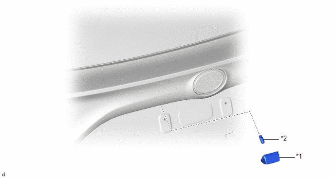
| *1 | LICENSE PLATE LIGHT LENS | *2 | LICENSE PLATE LIGHT BULB |
Removal
REMOVAL
CAUTION / NOTICE / HINT
HINT:
- Use the same procedure for the RH and LH sides.
- The procedure listed below is for the LH side.
PROCEDURE
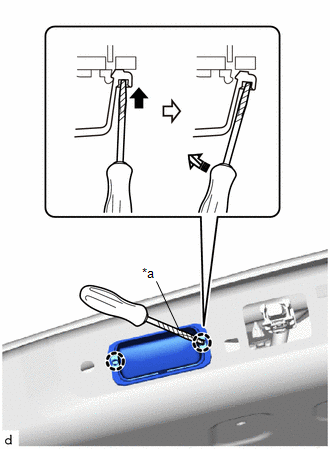
1. REMOVE LICENSE PLATE LIGHT LENS
| (a) Using a screwdriver with its tip wrapped in protective tape, disengage the claws to remove the license plate light lens as shown in the illustration. |
|
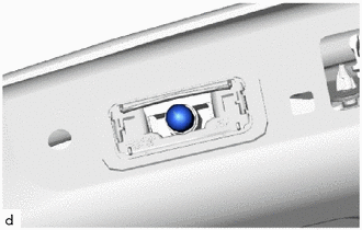
2. REMOVE LICENSE PLATE LIGHT BULB
| (a) Remove the license plate light bulb. |
|
Installation
INSTALLATION
CAUTION / NOTICE / HINT
HINT:
- Use the same procedure for the RH and LH sides.
- The procedure listed below is for the LH side.
PROCEDURE
1. INSTALL LICENSE PLATE LIGHT BULB
(a) Install the license plate light bulb.
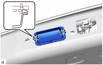
2. INSTALL LICENSE PLATE LIGHT LENS
| (a) Engage the claws to install the license plate light lens. |
|
 Gf1a Transfer Oil
ComponentsCOMPONENTS ILLUSTRATION
*1 NO. 1 ENGINE UNDER COVER ASSEMBLY *2 TRANSFER FILLER PLUG *3 TRANSFER DRAIN PLUG *4 GASKET
Tightening torque for "Major areas involving basic vehicle performance such as moving/turning/stopping": N*m (kgf*cm, ft...
 Rear Brake Flexible Hose
ComponentsCOMPONENTS ILLUSTRATION
*1 REAR FLEXIBLE HOSE *2 GASKET *3 UNION BOLT *4 BRAKE LINE
Tightening torque for "Major areas involving basic vehicle performance such as moving/turning/stopping": N*m (kgf*cm, ft...
Other information:
Toyota Yaris XP210 (2020-2026) Reapir and Service Manual: Customize Parameters
CUSTOMIZE PARAMETERS CUSTOMIZE LTA NOTICE: Record the settings when the vehicle is brought to the workshop so they can be restored. (a) Customizing with the Multi-information Display (1) Turn the ignition switch to ON. (2) Change the setting of the lane tracing assist system by operating the customize switch (steering pad switch)...
Toyota Yaris XP210 (2020-2026) Reapir and Service Manual: Freeze Frame Data
FREEZE FRAME DATA CHECK FREEZE FRAME DATA HINT: The ECU records vehicle and driving condition information as freeze frame data the moment a DTC is stored. (a) Enter the following menus: Powertrain / Radar Cruise 1*1 or Radar Cruise 2*2 / Trouble Codes...
Categories
- Manuals Home
- Toyota Yaris Owners Manual
- Toyota Yaris Service Manual
- Fuse Panel Description
- Battery Monitor Module General Electrical Failure (P058A01)
- Maintenance
- New on site
- Most important about car
Keys

To use the auxiliary key, press the knob and pull out the auxiliary key from the smart key.

Copyright © 2026 www.toyaris4.com