Toyota Yaris: Maintenance / Rear Brake Flexible Hose
Components
COMPONENTS
ILLUSTRATION
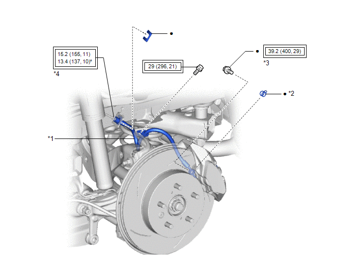
| *1 | REAR FLEXIBLE HOSE | *2 | GASKET |
| *3 | UNION BOLT | *4 | BRAKE LINE |
 | Tightening torque for "Major areas involving basic vehicle performance such as moving/turning/stopping": N*m (kgf*cm, ft.*lbf) | * | For use with a union nut wrench |
| ● | Non-reusable part | - | - |
Installation
INSTALLATION
CAUTION / NOTICE / HINT
HINT:
- Use the same procedure for the RH side and LH side.
- The following procedure is for the LH side.
PROCEDURE
1. INSTALL REAR FLEXIBLE HOSE
NOTICE:
When installing the rear flexible hose, minimize twisting of the hose.
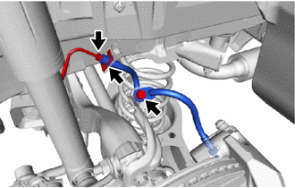
| (a) Install the rear flexible hose with a new clip. NOTICE:
|
|

(b) Using a union nut wrench, connect the brake line to the rear flexible hose while holding the rear flexible hose with a wrench.
Torque:
Specified tightening torque :
15.2 N·m {155 kgf·cm, 11 ft·lbf}
NOTICE:
- Do not kink or damage the brake line.
- Do not allow any foreign matter such as dirt or dust to enter the brake line from the connecting parts.
HINT:
-
Calculate the torque wrench reading when changing the fulcrum length of the torque wrench.
Click here

-
When using a union nut wrench (fulcrum length of 22 mm (0.866 in.)) + torque wrench (fulcrum length of 162 mm (6.38 in.)):
13.4 N*m (137 kgf*cm, 10 ft.*lbf)
(c) Install the rear flexible hose to the flexible hose bracket with the bolt.
Torque:
29 N·m {296 kgf·cm, 21 ft·lbf}
NOTICE:
Do not twist the rear flexible hose when installing it.
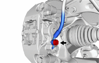
(d) Connect the rear flexible hose to the rear disc brake cylinder assembly with a new union bolt and a new gasket.
Torque:
39.2 N·m {400 kgf·cm, 29 ft·lbf}
NOTICE:
- Install the rear flexible hose lock securely into the lock hole in the rear disc brake cylinder assembly.
- Do not twist the rear flexible hose when installing it.
2. BLEED BRAKE LINE
Click here

3. INSTALL REAR WHEEL
Click here

Removal
REMOVAL
CAUTION / NOTICE / HINT
HINT:
- Use the same procedure for the RH side and LH side.
- The following procedure is for the LH side.
PROCEDURE
1. REMOVE REAR WHEEL
Click here

2. DRAIN BRAKE FLUID
NOTICE:
If brake fluid leaks onto any painted surface, immediately wash it off.
3. REMOVE REAR FLEXIBLE HOSE
| (a) Remove the union bolt and gasket, and disconnect the rear flexible hose from the rear disc brake cylinder assembly. |
|
| (b) Remove the bolt and separate the rear flexible hose from the flexible hose bracket. |
|
(c) Using a union nut wrench, disconnect the brake line while holding the rear flexible hose with a wrench.
NOTICE:
- Do not kink or damage the brake line.
- Do not allow any foreign matter such as dirt or dust to enter the brake line from the connecting parts.
(d) Remove the clip and rear flexible hose from the vehicle body.
 License Plate Light Bulb
ComponentsCOMPONENTS ILLUSTRATION
*1 LICENSE PLATE LIGHT LENS *2 LICENSE PLATE LIGHT BULB RemovalREMOVAL CAUTION / NOTICE / HINT HINT:
Use the same procedure for the RH and LH sides...

Other information:
Toyota Yaris XP210 (2020-2026) Reapir and Service Manual: Lost Communication with ECM/PCM "A" Missing Message (U010087,U010187,U012687,U012987,U015587)
DESCRIPTION The following DTCs are stored when there is a communication malfunction between the millimeter wave radar sensor and each sensor or ECU. DTC No. Detection Item DTC Detection Condition Trouble Area U010087 Lost Communication with ECM/PCM "A" Missing Message When the ignition switch is ON for 3 seconds or more, an ECM communication malfunction continues for approximately 3 seconds or more...
Toyota Yaris XP210 (2020-2026) Owner's Manual: Traction Control System (TCS)
The Traction Control System (TCS) enhances traction and safety by controlling engine torque and braking. When the TCS detects driving wheel slippage, it lowers engine torque and operates the brakes to prevent loss of traction. This means that on a slick surface, the engine adjusts automatically to provide optimum power to the drive wheels, limiting wheel spin and loss of traction...
Categories
- Manuals Home
- Toyota Yaris Owners Manual
- Toyota Yaris Service Manual
- Immobilizer System
- Removal
- Battery Monitor Module General Electrical Failure (P058A01)
- New on site
- Most important about car
Liftgate/Trunk Lid
WARNING
Never allow a person to ride in the luggage compartment/trunk
Allowing a person to ride in the luggage compartment/trunk is dangerous. The person in the luggage compartment/trunk could be seriously injured or killed during sudden braking or a collision.
Do not drive with the liftgate/trunk lid open