Toyota Yaris: Sfi System / Engine Coolant Temperature Sensor 1 Circuit Short to Ground (P011511)
DESCRIPTION
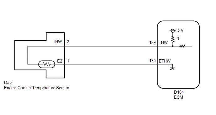
A thermistor, whose resistance value varies according to the engine coolant temperature, is built into the engine coolant temperature sensor. The structure of the sensor and its connection to the ECM are the same as those of the intake air temperature sensor.
Refer to DTC P011011.
Click here

HINT:
When DTC P011511 is stored, the ECM enters fail-safe mode. During fail-safe mode, the ECM sets the engine coolant temperature judgment value to 80°C (176°F) and the target engine coolant temperature to 82°C (180°F). Fail-safe mode continues until a pass condition is detected.
| DTC No. | Detection Item | DTC Detection Condition | Trouble Area | MIL | Note |
|---|---|---|---|---|---|
| P011511 | Engine Coolant Temperature Sensor 1 Circuit Short to Ground | The engine coolant temperature sensor output voltage is less than 0.142 V for 0.5 seconds or more (1 trip detection logic). |
| Comes on | SAE: P0117 |
HINT:
When a DTC is output, check the Data List item "Coolant Temperature" using the GTS.
Click here

| DTC No. | Coolant Temperature | Malfunction |
|---|---|---|
| P011511 | Higher than 135°C (275°F) | Short to ground in THW circuit |
If the Data List displays a normal value, the normal value may be due to a temporary recovery from the malfunction condition. Check for intermittent problems.
MONITOR DESCRIPTION
The engine coolant temperature sensor is used to monitor the outlet side engine coolant temperature. The engine coolant temperature sensor has a thermistor with a resistance that varies according to the temperature of the engine coolant. When the engine coolant temperature is low, the resistance in the thermistor increases. When the temperature is high, the resistance decreases. These variations in resistance are reflected in the output voltage from the sensor. The ECM monitors the sensor voltage and uses this value to calculate the engine coolant temperature. If the engine coolant temperature sensor output voltage deviates from the normal operating range, the ECM interprets this as a malfunction in the engine coolant temperature sensor circuit, illuminates the MIL and stores a DTC.
Example:
If the engine coolant temperature sensor output voltage is less than 0.142 V for 0.5 seconds or more, the ECM will illuminate the MIL and store this DTC.
MONITOR STRATEGY
| Frequency of Operation | Continuous |
CONFIRMATION DRIVING PATTERN
- Connect the GTS to the DLC3.
- Turn the ignition switch to ON.
- Turn the GTS on.
- Clear the DTCs (even if no DTCs are stored, perform the clear DTC procedure).
- Turn the ignition switch off and wait for at least 30 seconds.
- Turn the ignition switch to ON.
- Turn the GTS on.
- Wait 5 seconds or more.
- Enter the following menus: Powertrain / Engine / Trouble Codes.
-
Read the pending DTCs.
HINT:
- If a pending DTC is output, the system is malfunctioning.
- If a pending DTC is not output, perform the following procedure.
- Enter the following menus: Powertrain / Engine / Utility / All Readiness.
- Input the DTC: P011511.
-
Check the DTC judgment result.
GTS Display
Description
NORMAL
- DTC judgment completed
- System normal
ABNORMAL
- DTC judgment completed
- System abnormal
INCOMPLETE
- DTC judgment not completed
- Perform driving pattern after confirming DTC enabling conditions
HINT:
- If the judgment result is NORMAL, the system is normal.
- If the judgment result is ABNORMAL, the system is malfunctioning.
WIRING DIAGRAM
CAUTION / NOTICE / HINT
HINT:
- If DTC P011511 is stored, check that the engine does not overheat (DTC P011511 may be stored due to engine overheating).
- Read Freeze Frame Data using the GTS. The ECM records vehicle and driving condition information as Freeze Frame Data the moment a DTC is stored. When troubleshooting, Freeze Frame Data can help determine if the vehicle was moving or stationary, if the engine was warmed up or not, if the air fuel ratio was lean or rich, and other data from the time the malfunction occurred.
PROCEDURE
| 1. | READ VALUE USING GTS (CHECK FOR SHORT IN WIRE HARNESS) |
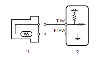
| *1 | Engine Coolant Temperature Sensor |
| *2 | ECM |
(a) Disconnect the engine coolant temperature sensor connector.
(b) Enter the following menus.
Powertrain > Engine > Data List| Tester Display |
|---|
| Coolant Temperature |
(c) According to the display on the GTS, read the Data List.
OK:
| GTS Display | Specified Condition |
|---|---|
| Coolant Temperature | -40°C (-40°F) |
HINT:
Perform "Inspection After Repair" after replacing the engine coolant temperature sensor.
Click here

| OK |
 | REPLACE ENGINE COOLANT TEMPERATURE SENSOR |
|

| 2. | CHECK HARNESS AND CONNECTOR (ENGINE COOLANT TEMPERATURE SENSOR - ECM) |
(a) Disconnect the engine coolant temperature sensor connector.
(b) Disconnect the ECM connector.
(c) Measure the resistance according to the value(s) in the table below.
Standard Resistance:
| Tester Connection | Condition | Specified Condition |
|---|---|---|
| D35-2(THW) or D104-129(THW) - Body ground and other terminals | Always | 10 kΩ or higher |
| OK |
 | REPLACE ECM |
| NG |
 | REPAIR OR REPLACE HARNESS OR CONNECTOR |
 Intake Air Temperature Sensor 1 Bank 1 Circuit Short to Battery or Open (P011015)
DESCRIPTION Refer to DTC P011011. Click here
HINT: When DTC P011015 is stored, the ECM enters fail-safe mode. During fail-safe mode, the intake air temperature is estimated to be 20°C (68°F) by the ECM...
 Engine Coolant Temperature Sensor 1 Signal Stuck in Range (P01152A)
DESCRIPTION Refer to DTC P011511. Click here
DTC No. Detection Item DTC Detection Condition Trouble Area MIL Note P01152A Engine Coolant Temperature Sensor 1 Signal Stuck in Range Either of the following conditions is met (2 trip detection logic):
When engine is started cold and warmed up, the engine coolant temperature sensor value does not change...
Other information:
Toyota Yaris XP210 (2020-2026) Reapir and Service Manual: Lost Communication with ECM/PCM "A" Missing Message (U010087,U012687,U012987,U015587)
DESCRIPTION The millimeter wave radar sensor assembly communicates with each sensor and ECU via CAN communication. If any malfunction is detected in a CAN communication circuit, one or more CAN communication system DTCs are stored. DTC No. Detection Item DTC Detection Condition Trouble Area DTC Output from U010087 Lost Communication with ECM/PCM "A" Missing Message When the dynamic radar cruise control system is operating, a communication malfunction between the ECM and millimeter wave radar sensor assembly is detected for 1 second or more...
Toyota Yaris XP210 (2020-2026) Owner's Manual: Pictorial Index
I..
Categories
- Manuals Home
- Toyota Yaris Owners Manual
- Toyota Yaris Service Manual
- Fuse Panel Description
- Auto Lock/Unlock Function
- Key Battery Replacement
- New on site
- Most important about car
Fuel-Filler Lid and Cap
WARNING
When removing the fuel-filler cap, loosen the cap slightly and wait for any hissing to stop, then remove it
Fuel spray is dangerous. Fuel can burn skin and eyes and cause illness if ingested. Fuel spray is released when there is pressure in the fuel tank and the fuel-filler cap is removed too quickly.