Toyota Yaris: Sfi System / Intake Air Temperature Sensor 1 Bank 1 Circuit Short to Battery or Open (P011015)
DESCRIPTION
Refer to DTC P011011.
Click here

HINT:
When DTC P011015 is stored, the ECM enters fail-safe mode. During fail-safe mode, the intake air temperature is estimated to be 20°C (68°F) by the ECM. Fail-safe mode continues until a pass condition is detected, and the ignition switch is then turned off.
| DTC No. | Detection Item | DTC Detection Condition | Trouble Area | MIL | Note |
|---|---|---|---|---|---|
| P011015 | Intake Air Temperature Sensor 1 Bank 1 Circuit Short to Battery or Open | The intake air temperature sensor output voltage is higher than 4.91 V for 0.5 seconds or more (1 trip detection logic). |
| Comes on | SAE: P0113 |
HINT:
When a DTC is output, check the Data List item "Intake Air Temperature" using the GTS.
Click here

| DTC No. | Intake Air Temperature | Malfunction |
|---|---|---|
| P011015 | -40°C (-40°F) |
|
If the Data List displays a normal value, the normal value may be due to a temporary recovery from the malfunction condition. Check for intermittent problems.
MONITOR DESCRIPTION
The ECM monitors the sensor voltage and uses this value to calculate the intake air temperature. When the intake air temperature sensor output voltage deviates from the normal operating range, the ECM interprets this as a malfunction in the intake air temperature sensor circuit, illuminates the MIL and stores a DTC.
Example:
If the intake air temperature sensor output voltage is higher than 4.91 V for 0.5 seconds or more, the ECM will illuminate the MIL and store this DTC.
MONITOR STRATEGY
| Frequency of Operation | Continuous |
CONFIRMATION DRIVING PATTERN
- Connect the GTS to the DLC3.
- Turn the ignition switch to ON.
- Turn the GTS on.
- Clear the DTCs (even if no DTCs are stored, perform the clear DTC procedure).
- Turn the ignition switch off and wait for at least 30 seconds.
- Turn the ignition switch to ON.
- Turn the GTS on.
- Wait 0.5 seconds or more.
- Enter the following menus: Powertrain / Engine / Trouble Codes.
-
Read the pending DTCs.
HINT:
- If a pending DTC is output, the system is malfunctioning.
- If a pending DTC is not output, perform the following procedure.
- Enter the following menus: Powertrain / Engine / Utility / All Readiness.
- Input the DTC: P011015.
-
Check the DTC judgment result.
GTS Display
Description
NORMAL
- DTC judgment completed
- System normal
ABNORMAL
- DTC judgment completed
- System abnormal
INCOMPLETE
- DTC judgment not completed
- Perform driving pattern after confirming DTC enabling conditions
HINT:
- If the judgment result is NORMAL, the system is normal.
- If the judgment result is ABNORMAL, the system is malfunctioning.
WIRING DIAGRAM
Refer to DTC P010012.
Click here

CAUTION / NOTICE / HINT
HINT:
Read Freeze Frame Data using the GTS. The ECM records vehicle and driving condition information as Freeze Frame Data the moment a DTC is stored. When troubleshooting, Freeze Frame Data can help determine if the vehicle was moving or stationary, if the engine was warmed up or not, if the air fuel ratio was lean or rich, and other data from the time the malfunction occurred.
PROCEDURE
| 1. | READ VALUE USING GTS (CHECK FOR OPEN IN WIRE HARNESS) |
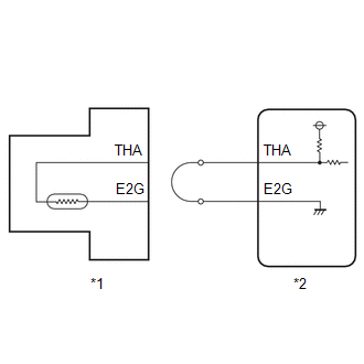
| *1 | Mass air flow meter sub-assembly |
| *2 | ECM |
(a) Disconnect the mass air flow meter sub-assembly connector.
(b) Connect terminals 4 (THA) and 2 (E2G) of the mass air flow meter sub-assembly connector on the wire harness side.
(c) Enter the following menus.
Powertrain > Engine > Data List| Tester Display |
|---|
| Intake Air Temperature |
(d) According to the display on the GTS, read the Data List.
Standard value:
Higher than 128°C (262°F)
HINT:
Perform "Inspection After Repair" after replacing the mass air flow meter sub-assembly.
Click here

| OK |
 | REPLACE MASS AIR FLOW METER SUB-ASSEMBLY |
|

| 2. | CHECK HARNESS AND CONNECTOR (MASS AIR FLOW METER SUB-ASSEMBLY - ECM) |
(a) Disconnect the mass air flow meter sub-assembly connector.
(b) Disconnect the ECM connector.
(c) Measure the resistance according to the value(s) in the table below.
Standard Resistance:
| Tester Connection | Condition | Specified Condition |
|---|---|---|
| D23-4(THA) - D104-106(THA) | Always | Below 1 Ω |
| D23-2(E2G) - D104-83(E2G) | Always | Below 1 Ω |
| D23-4(THA) or D104-106(THA) - Other terminals | Always | 10 kΩ or higher |
| OK |
 | REPLACE ECM |
| NG |
 | REPAIR OR REPLACE HARNESS OR CONNECTOR |
 Intake Air Temperature Sensor 1 Bank 1 Circuit Short to Ground (P011011)
DESCRIPTION
The intake air temperature sensor, mounted on the mass air flow meter sub-assembly, monitors the intake air temperature. The intake air temperature sensor has a built-in thermistor with a resistance that varies according to the temperature of the intake air...
 Engine Coolant Temperature Sensor 1 Circuit Short to Ground (P011511)
DESCRIPTION A thermistor, whose resistance value varies according to the engine coolant temperature, is built into the engine coolant temperature sensor...
Other information:
Toyota Yaris XP210 (2020-2025) Reapir and Service Manual: Removal
REMOVAL CAUTION / NOTICE / HINT The necessary procedures (adjustment, calibration, initialization, or registration) that must be performed after parts are removed and installed, or replaced during the rear No. 1 differential mount cushion replacement are shown below...
Toyota Yaris XP210 (2020-2025) Reapir and Service Manual: Diagnostic Trouble Code Chart
D..
Categories
- Manuals Home
- Toyota Yaris Owners Manual
- Toyota Yaris Service Manual
- Maintenance
- Auto Lock/Unlock Function
- Engine & Hybrid System
- New on site
- Most important about car
Key Suspend Function
If a key is left in the vehicle, the functions of the key left in the vehicle are temporarily suspended to prevent theft of the vehicle.
To restore the functions, press the unlock button on the functions-suspended key in the vehicle.