Toyota Yaris: Differential Mount Cushion / Removal
REMOVAL
CAUTION / NOTICE / HINT
The necessary procedures (adjustment, calibration, initialization, or registration) that must be performed after parts are removed and installed, or replaced during the rear No. 1 differential mount cushion replacement are shown below.
Necessary Procedure After Parts Removed/Installed/Replaced| Replaced Part or Performed Procedure | Necessary Procedure | Effect/Inoperative Function when Necessary Procedure not Performed | Link |
|---|---|---|---|
| Gas leaks from exhaust system | Inspection after repair |
|
|
| Rear wheel alignment adjustment | Calibration |
|
|


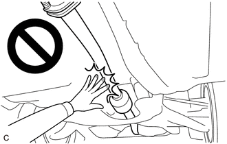
CAUTION:
-
To prevent burns, do not touch the engine, exhaust pipe or other high temperature components while the engine is hot.
-
The rear differential carrier assembly is very heavy. Be sure to follow the procedure described in the repair manual, or the engine lifter may suddenly drop or the rear differential carrier assembly may fall off the engine lifter.
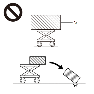
*a
An Object Exceeding Weight Limit of Engine Lifter
PROCEDURE
1. REMOVE REAR DIFFERENTIAL CARRIER ASSEMBLY
Click here

2. REMOVE REAR NO. 1 DIFFERENTIAL MOUNT CUSHION
(a) Using SST, remove the rear No. 1 differential mount cushion.
SST: 09316-20011
SST: 09570-24011
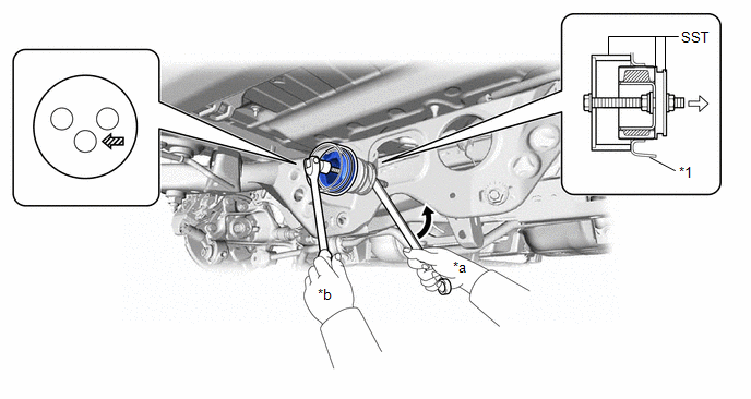
| *1 | Rear Suspension Member Sub-assembly | - | - |
| *a | Turn | *b | Hold |
 | Turning Direction |
 | Front of Vehicle |
 | SST Bolt Position | - | - |
NOTICE:
- Do not bring SST into contact with the rear suspension member sub-assembly.
- Before using SST, apply grease to SST bolt.
- Set SST in the correct direction.
- Do not tilt the bolt of SST.
- Do not reuse the rear No. 1 differential mount cushion.
 Components
C..
 Installation
INSTALLATION PROCEDURE 1. INSTALL REAR NO. 1 DIFFERENTIAL MOUNT CUSHION (a) Using SST, install a new rear No. 1 differential mount cushion. SST: 09316-20011 SST: 09570-24011
*1 Rear Suspension Member Sub-assembly - - *a 0° +/- 3° *b 15...
Other information:
Toyota Yaris XP210 (2020-2026) Reapir and Service Manual: On-vehicle Inspection
ON-VEHICLE INSPECTION PROCEDURE 1. INSPECT CANISTER (FUEL SUCTION PLATE SUB-ASSEMBLY) (for Fuel Tank Cap Method) (a) Inspect evaporative emission control system. Click here (b) Check for clogs in the air filter (when not using the GTS). (1) Start the engine...
Toyota Yaris XP210 (2020-2026) Reapir and Service Manual: Problem Symptoms Table
PROBLEM SYMPTOMS TABLE NOTICE: If the main body ECU (multiplex network body ECU) is replaced, refer to the Registration. Click here HINT: Troubleshooting of the theft deterrent system is based on the premise that the power door lock control system and the wireless door lock control system are operating normally...
Categories
- Manuals Home
- Toyota Yaris Owners Manual
- Toyota Yaris Service Manual
- Brake System Control Module "A" System Voltage System Voltage Low (C137BA2)
- Removal
- Diagnostic Trouble Code Chart
- New on site
- Most important about car
Supplemental Restraint System (SRS) Precautions
The front and side supplemental restraint systems (SRS) include different types of air bags. Please verify the different types of air bags which are equipped on your vehicle by locating the “SRS AIRBAG” location indicators. These indicators are visible in the area where the air bags are installed.
The air bags are installed in the following locations:
The steering wheel hub (driver air bag) The front passenger dashboard (front passenger air bag) The outboard sides of the front seatbacks (side air bags) The front and rear window pillars, and the roof edge along both sides (curtain air bags)