Toyota Yaris: Sfi System / Intake Air Temperature Sensor 1 Bank 1 Circuit Short to Ground (P011011)
DESCRIPTION
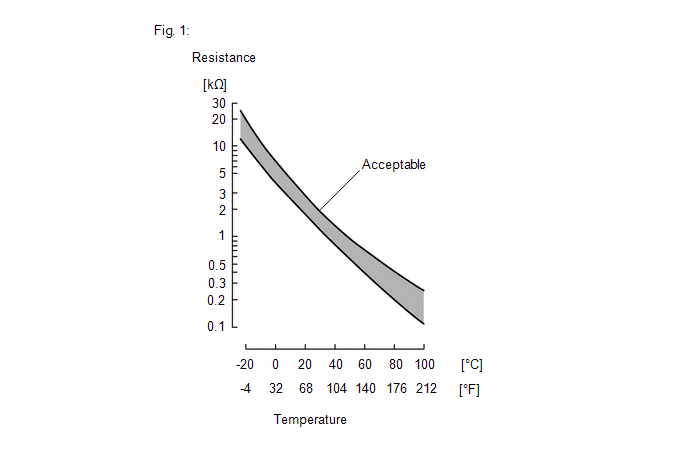
The intake air temperature sensor, mounted on the mass air flow meter sub-assembly, monitors the intake air temperature. The intake air temperature sensor has a built-in thermistor with a resistance that varies according to the temperature of the intake air. When the intake air temperature is low, the resistance of the thermistor increases. When the temperature is high, the resistance drops. These variations in resistance are transmitted to the ECM as voltage changes (see Fig. 1).
The intake air temperature sensor is powered by a 5 V supply from the THA terminal of the ECM, via resistor R.
Resistor R and the intake air temperature sensor are connected in series. When the resistance value of the intake air temperature sensor changes, according to changes in the intake air temperature, the voltage at terminal THA also varies. Based on this signal, the ECM increases the fuel injection volume when the engine is cold to improve driveability.
HINT:
When DTC P011011 is stored, the ECM enters fail-safe mode. During fail-safe mode, the intake air temperature is estimated to be 20°C (68°F) by the ECM. Fail-safe mode continues until a pass condition is detected, and the ignition switch is then turned off.
| DTC No. | Detection Item | DTC Detection Condition | Trouble Area | MIL | Note |
|---|---|---|---|---|---|
| P011011 | Intake Air Temperature Sensor 1 Bank 1 Circuit Short to Ground | The intake air temperature sensor output voltage is less than 0.142 V for 0.5 seconds or more (1 trip detection logic). |
| Comes on | SAE: P0112 |
HINT:
When a DTC is output, check the Data List item "Intake Air Temperature" using the GTS.
Click here

| DTC No. | Intake Air Temperature | Malfunction |
|---|---|---|
| P011011 | Higher than 128°C (262°F) | Short to ground in THA circuit |
If the Data List displays a normal value, the normal value may be due to a temporary recovery from the malfunction condition. Check for intermittent problems.
MONITOR DESCRIPTION
The ECM monitors the sensor voltage and uses this value to calculate the intake air temperature. When the sensor output voltage deviates from the normal operating range, the ECM interprets this as a malfunction in the intake air temperature sensor (mass air flow meter sub-assembly) circuit, illuminates the MIL and stores a DTC.
Example:
If the intake air temperature sensor output voltage is less than 0.142 V for 0.5 seconds or more, the ECM will illuminate the MIL and store this DTC.
MONITOR STRATEGY
| Frequency of Operation | Continuous |
CONFIRMATION DRIVING PATTERN
- Connect the GTS to the DLC3.
- Turn the ignition switch to ON.
- Turn the GTS on.
- Clear the DTCs (even if no DTCs are stored, perform the clear DTC procedure).
- Turn the ignition switch off and wait for at least 30 seconds.
- Turn the ignition switch to ON.
- Turn the GTS on.
- Wait 0.5 seconds or more.
- Enter the following menus: Powertrain / Engine / Trouble Codes.
-
Read the pending DTCs.
HINT:
- If a pending DTC is output, the system is malfunctioning.
- If a pending DTC is not output, perform the following procedure.
- Enter the following menus: Powertrain / Engine / Utility / All Readiness.
- Input the DTC: P011011.
-
Check the DTC judgment result.
GTS Display
Description
NORMAL
- DTC judgment completed
- System normal
ABNORMAL
- DTC judgment completed
- System abnormal
INCOMPLETE
- DTC judgment not completed
- Perform driving pattern after confirming DTC enabling conditions
HINT:
- If the judgment result is NORMAL, the system is normal.
- If the judgment result is ABNORMAL, the system is malfunctioning.
WIRING DIAGRAM
Refer to DTC P010012.
Click here

CAUTION / NOTICE / HINT
HINT:
Read Freeze Frame Data using the GTS. The ECM records vehicle and driving condition information as Freeze Frame Data the moment a DTC is stored. When troubleshooting, Freeze Frame Data can help determine if the vehicle was moving or stationary, if the engine was warmed up or not, if the air fuel ratio was lean or rich, and other data from the time the malfunction occurred.
PROCEDURE
| 1. | READ VALUE USING GTS (CHECK FOR SHORT IN WIRE HARNESS) |
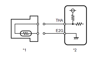
| *1 | Mass Air Flow Meter Sub-assembly |
| *2 | ECM |
(a) Disconnect the mass air flow meter sub-assembly connector.
(b) Enter the following menus.
Powertrain > Engine > Data List| Tester Display |
|---|
| Intake Air Temperature |
(c) According to the display on the GTS, read the Data List.
OK:
| GTS Display | Specified Condition |
|---|---|
| Intake Air Temperature | -40°C (-40°F) |
HINT:
Perform "Inspection After Repair" after replacing the mass air flow meter sub-assembly.
Click here

| OK |
 | REPLACE MASS AIR FLOW METER SUB-ASSEMBLY |
|

| 2. | CHECK HARNESS AND CONNECTOR (MASS AIR FLOW METER SUB-ASSEMBLY - ECM) |
(a) Disconnect the mass air flow meter sub-assembly connector.
(b) Disconnect the ECM connector.
(c) Measure the resistance according to the value(s) in the table below.
Standard Resistance:
| Tester Connection | Condition | Specified Condition |
|---|---|---|
| D23-4(THA) or D104-106(THA) - Body ground and other terminals | Always | 10 kΩ or higher |
| OK |
 | REPLACE ECM |
| NG |
 | REPAIR OR REPLACE HARNESS OR CONNECTOR |
 Manifold Absolute Pressure / Barometric Pressure Sensor Circuit Short to Battery or Open (P010515)
DESCRIPTION Refer to DTC P010511. Click here
DTC No. Detection Item DTC Detection Condition Trouble Area MIL Note P010515 Manifold Absolute Pressure / Barometric Pressure Sensor Circuit Short to Battery or Open The No...
 Intake Air Temperature Sensor 1 Bank 1 Circuit Short to Battery or Open (P011015)
DESCRIPTION Refer to DTC P011011. Click here
HINT: When DTC P011015 is stored, the ECM enters fail-safe mode. During fail-safe mode, the intake air temperature is estimated to be 20°C (68°F) by the ECM...
Other information:
Toyota Yaris XP210 (2020-2025) Reapir and Service Manual: Engine Hood Courtesy Switch Circuit
DESCRIPTION The engine stop and start ECU detects whether the engine hood is open or closed based on a signal received from the engine hood courtesy switch built into the hood lock assembly. The engine stop and start ECU prohibits starting of the engine by stop and start control and changes the mode to "stalled" if the engine hood is open with the clutch pedal is released while the engine is stopped by stop and start control...
Toyota Yaris XP210 (2020-2025) Reapir and Service Manual: Inspection
INSPECTION PROCEDURE 1. INSPECT FOG LIGHT ASSEMBLY LH (a) Check that the fog light assembly LH. (1) Apply auxiliary battery voltage to the fog light assembly LH and check that the light comes on. OK: Condition Specified Condition A104-2 (B) - Auxiliary battery positive (+) A104-1 (E) - Auxiliary battery negative (-) Fog light assembly LH comes on If the result is not as specified, replace the fog light assembly LH...
Categories
- Manuals Home
- Toyota Yaris Owners Manual
- Toyota Yaris Service Manual
- How to connect USB port/Auxiliary jack
- Fuse Panel Description
- Adjustment
- New on site
- Most important about car
Refueling
Before refueling, close all the doors, windows, and the liftgate/trunk lid, and switch the ignition OFF.
To open the fuel-filler lid, pull the remote fuel-filler lid release.
