Toyota Yaris: Sfi System / Manifold Absolute Pressure / Barometric Pressure Sensor Circuit Short to Battery or Open (P010515)
DESCRIPTION
Refer to DTC P010511.
Click here

| DTC No. | Detection Item | DTC Detection Condition | Trouble Area | MIL | Note |
|---|---|---|---|---|---|
| P010515 | Manifold Absolute Pressure / Barometric Pressure Sensor Circuit Short to Battery or Open | The No. 1 turbo pressure sensor output voltage is higher than 4.2 V for 3 seconds or more (1 trip detection logic). |
| Comes on | SAE: P0108 |
HINT:
When a DTC is output, check the Data List item "Intake Manifold Absolute Pressure" using the GTS.
Click here

| DTC No. | Intake Manifold Absolute Pressure | Malfunction |
|---|---|---|
| P010515 | Higher than 278 kPa (40.31 psi) |
|
If the Data List displays a normal value, the normal value may be due to a temporary recovery from the malfunction condition. Check for intermittent problems.
MONITOR DESCRIPTION
The ECM monitors the No. 1 turbo pressure sensor voltage and uses this value to calculate the intake manifold pressure. When the No. 1 turbo pressure sensor output voltage deviates from the normal operating range, the ECM interprets this as a malfunction in the No. 1 turbo pressure sensor circuit, illuminates the MIL and stores a DTC.
Example:
If the sensor output voltage is higher than 4.2 V for 3 seconds or more, the ECM stores this DTC.
MONITOR STRATEGY
| Frequency of Operation | Continuous |
CONFIRMATION DRIVING PATTERN
- Connect the GTS to the DLC3.
- Turn the ignition switch to ON.
- Turn the GTS on.
- Clear the DTCs (even if no DTCs are stored, perform the clear DTC procedure).
- Turn the ignition switch off and wait for at least 30 seconds.
- Start the engine and wait 5 seconds or more.
- Turn the GTS on.
- Enter the following menus: Powertrain / Engine / Trouble Codes.
-
Read the pending DTCs.
HINT:
- If a pending DTC is output, the system is malfunctioning.
- If a pending DTC is not output, perform the following procedure.
- Enter the following menus: Powertrain / Engine / Utility / All Readiness.
- Input the DTC: P010515.
-
Check the DTC judgment result.
GTS Display
Description
NORMAL
- DTC judgment completed
- System normal
ABNORMAL
- DTC judgment completed
- System abnormal
INCOMPLETE
- DTC judgment not completed
- Perform driving pattern after confirming DTC enabling conditions
HINT:
- If the judgment result is NORMAL, the system is normal.
- If the judgment result is ABNORMAL, the system is malfunctioning.
WIRING DIAGRAM
Refer to DTC P010511.
Click here

CAUTION / NOTICE / HINT
HINT:
Read Freeze Frame Data using the GTS. The ECM records vehicle and driving condition information as Freeze Frame Data the moment a DTC is stored. When troubleshooting, Freeze Frame Data can help determine if the vehicle was moving or stationary, if the engine was warmed up or not, if the air fuel ratio was lean or rich, and other data from the time the malfunction occurred.
PROCEDURE
| 1. | CHECK HARNESS AND CONNECTOR |
HINT:
Make sure that the connector is properly connected. If it is not, securely connect it and check for DTCs again.
(a) Disconnect the No. 1 turbo pressure sensor connector.
(b) Turn the ignition switch to ON.
| (c) Measure the voltage according to the value(s) in the table below. Standard Voltage:
|
|
(d) Turn the ignition switch off and wait for at least 30 seconds.
(e) Measure the resistance according to the value(s) in the table below.
Standard Resistance:
| Tester Connection | Condition | Specified Condition |
|---|---|---|
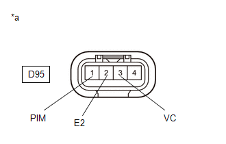
| D95-2(E2) - Body ground | Always | Below 1 Ω |
| D95-3(VC) - D95-1(PIM) | Ignition switch off | 171 to 189 kΩ |
| OK |
 | REPLACE NO. 1 TURBO PRESSURE SENSOR |
|

| 2. | CHECK HARNESS AND CONNECTOR (NO. 1 TURBO PRESSURE SENSOR - ECM) |
(a) Disconnect the No. 1 turbo pressure sensor connector.
(b) Disconnect the ECM connector.
(c) Measure the resistance according to the value(s) in the table below.
Standard Resistance:
| Tester Connection | Condition | Specified Condition |
|---|---|---|
| D95-2(E2) - D104-76(EPIM) | Always | Below 1 Ω |
| D95-1(PIM) - D104-98(PIM) | Always | Below 1 Ω |
| D95-1(PIM) or D104-98(PIM) - Other terminals | Always | 10 kΩ or higher |
| OK |
 | REPLACE ECM |
| NG |
 | REPAIR OR REPLACE HARNESS OR CONNECTOR |
 Manifold Absolute Pressure / Barometric Pressure Sensor Circuit Short to Ground (P010511)
DESCRIPTION
The No. 1 turbo pressure sensor detects the intake manifold pressure as a change in voltage. The ECM calculates the intake manifold pressure based on this voltage...
 Intake Air Temperature Sensor 1 Bank 1 Circuit Short to Ground (P011011)
DESCRIPTION
The intake air temperature sensor, mounted on the mass air flow meter sub-assembly, monitors the intake air temperature. The intake air temperature sensor has a built-in thermistor with a resistance that varies according to the temperature of the intake air...
Other information:
Toyota Yaris XP210 (2020-2025) Reapir and Service Manual: Inspection
INSPECTION PROCEDURE 1. INSPECT FRONT SEAT INNER BELT ASSEMBLY (for Driver Side) (a) Check the resistance. (1) Measure the resistance according to the value(s) in the table below. Standard Resistance: Tester Connection Condition Specified Condition If the result is not as specified, replace the front seat inner belt assembly...
Toyota Yaris XP210 (2020-2025) Reapir and Service Manual: Engine Coolant Temperature Receiver Gauge Malfunction
DESCRIPTION In this circuit, the combination meter assembly receives engine coolant temperature signals from the ECM via CAN communication. The combination meter assembly displays an engine coolant temperature warning based on the data received from the ECM...
Categories
- Manuals Home
- Toyota Yaris Owners Manual
- Toyota Yaris Service Manual
- Immobilizer System
- Key Battery Replacement
- Fuel Gauge
- New on site
- Most important about car
Liftgate/Trunk Lid
WARNING
Never allow a person to ride in the luggage compartment/trunk
Allowing a person to ride in the luggage compartment/trunk is dangerous. The person in the luggage compartment/trunk could be seriously injured or killed during sudden braking or a collision.
Do not drive with the liftgate/trunk lid open