Toyota Yaris: Sfi System / Manifold Absolute Pressure / Barometric Pressure Sensor Circuit Short to Ground (P010511)
DESCRIPTION
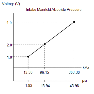
The No. 1 turbo pressure sensor detects the intake manifold pressure as a change in voltage. The ECM calculates the intake manifold pressure based on this voltage.
| DTC No. | Detection Item | DTC Detection Condition | Trouble Area | MIL | Note |
|---|---|---|---|---|---|
| P010511 | Manifold Absolute Pressure / Barometric Pressure Sensor Circuit Short to Ground | The No. 1 turbo pressure sensor output voltage is less than 0.9 V for 3 seconds or more (1 trip detection logic). |
| Comes on | SAE: P0107 |
HINT:
When a DTC is output, check the Data List item "Intake Manifold Absolute Pressure" using the GTS.
Click here

| DTC No. | Intake Manifold Absolute Pressure | Malfunction |
|---|---|---|
| P010511 | Approximately 0 kPa (0 psi) |
|
If the Data List displays a normal value, the normal value may be due to a temporary recovery from the malfunction condition. Check for intermittent problems.
MONITOR DESCRIPTION
The ECM monitors the No. 1 turbo pressure sensor voltage and uses this value to calculate the intake manifold pressure. When the No. 1 turbo pressure sensor output voltage deviates from the normal operating range, the ECM interprets this as a malfunction in the No. 1 turbo pressure sensor circuit, illuminates the MIL and stores a DTC.
Example:
If the sensor output voltage is less than 0.9 V for 3 seconds or more, the ECM stores this DTC.
MONITOR STRATEGY
| Frequency of Operation | Continuous |
CONFIRMATION DRIVING PATTERN
- Connect the GTS to the DLC3.
- Turn the ignition switch to ON.
- Turn the GTS on.
- Clear the DTCs (even if no DTCs are stored, perform the clear DTC procedure).
- Turn the ignition switch off and wait for at least 30 seconds.
- Start the engine and wait 5 seconds or more.
- Turn the GTS on.
- Enter the following menus: Powertrain / Engine / Trouble Codes.
-
Read the pending DTCs.
HINT:
- If a pending DTC is output, the system is malfunctioning.
- If a pending DTC is not output, perform the following procedure.
- Enter the following menus: Powertrain / Engine / Utility / All Readiness.
- Input the DTC: P010511.
-
Check the DTC judgment result.
GTS Display
Description
NORMAL
- DTC judgment completed
- System normal
ABNORMAL
- DTC judgment completed
- System abnormal
INCOMPLETE
- DTC judgment not completed
- Perform driving pattern after confirming DTC enabling conditions
HINT:
- If the judgment result is NORMAL, the system is normal.
- If the judgment result is ABNORMAL, the system is malfunctioning.
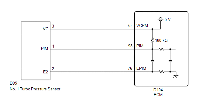
WIRING DIAGRAM
CAUTION / NOTICE / HINT
HINT:
Read Freeze Frame Data using the GTS. The ECM records vehicle and driving condition information as Freeze Frame Data the moment a DTC is stored. When troubleshooting, Freeze Frame Data can help determine if the vehicle was moving or stationary, if the engine was warmed up or not, if the air fuel ratio was lean or rich, and other data from the time the malfunction occurred.
PROCEDURE
| 1. | CHECK HARNESS AND CONNECTOR |
HINT:
Make sure that the connector is properly connected. If it is not, securely connect it and check for DTCs again.
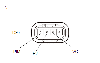
(a) Disconnect the No. 1 turbo pressure sensor connector.
(b) Turn the ignition switch to ON.
| (c) Measure the voltage according to the value(s) in the table below. Standard Voltage:
|
|
(d) Turn the ignition switch off and wait for at least 30 seconds.
(e) Measure the resistance according to the value(s) in the table below.
Standard Resistance:
| Tester Connection | Condition | Specified Condition |
|---|---|---|
| D95-3(VC) - D95-1(PIM) | Ignition switch off | 171 to 189 kΩ |
| OK |
 | REPLACE NO. 1 TURBO PRESSURE SENSOR |
|

| 2. | CHECK HARNESS AND CONNECTOR (NO. 1 TURBO PRESSURE SENSOR - ECM) |
(a) Disconnect the No. 1 turbo pressure sensor connector.
(b) Disconnect the ECM connector.
(c) Measure the resistance according to the value(s) in the table below.
Standard Resistance:
| Tester Connection | Condition | Specified Condition |
|---|---|---|
| D95-3(VC) - D104-75(VCPM) | Always | Below 1 Ω |
| D95-1(PIM) or D104-98(PIM) - Body ground and other terminals | Always | 10 kΩ or higher |
| OK |
 | REPLACE ECM |
| NG |
 | REPAIR OR REPLACE HARNESS OR CONNECTOR |
 Mass or Volume Air Flow Sensor "A" Circuit Short to Battery (P010012,P010014)
DESCRIPTION The mass air flow meter sub-assembly is a sensor that measures the intake air volume using the following built-in components:
By-pass passage (allows some of the intake air to flow past a silicon chip sensor)
Silicon chip sensor (uses a heater control bridge circuit and temperature sensor bridge circuit to detect the difference in the temperature of the intake air that passes the sensors positioned before and after the heater)...
 Manifold Absolute Pressure / Barometric Pressure Sensor Circuit Short to Battery or Open (P010515)
DESCRIPTION Refer to DTC P010511. Click here
DTC No. Detection Item DTC Detection Condition Trouble Area MIL Note P010515 Manifold Absolute Pressure / Barometric Pressure Sensor Circuit Short to Battery or Open The No...
Other information:
Toyota Yaris XP210 (2020-2025) Reapir and Service Manual: Catalyst System Efficiency Below Threshold Bank 1 (P042000)
MONITOR DESCRIPTION The ECM uses air fuel ratio sensors mounted in front of and behind the Three-Way Catalytic Converter (TWC) to monitor its efficiency. The first sensor, the air fuel ratio sensor (sensor 1), sends pre-catalyst information to the ECM...
Toyota Yaris XP210 (2020-2025) Reapir and Service Manual: Installation
INSTALLATION CAUTION / NOTICE / HINT HINT: Use the same procedure for the RH side and LH side. The following procedure is for the LH side. The front speed sensor rotor is a component of the front axle hub sub-assembly. If the front speed sensor rotor is malfunctioning, replace the front axle hub sub-assembly...
Categories
- Manuals Home
- Toyota Yaris Owners Manual
- Toyota Yaris Service Manual
- Adjustment
- G16e-gts (engine Mechanical)
- Fuel Gauge
- New on site
- Most important about car
Keys

To use the auxiliary key, press the knob and pull out the auxiliary key from the smart key.
