Toyota Yaris: Stop And Start System / Engine Hood Courtesy Switch Circuit
DESCRIPTION
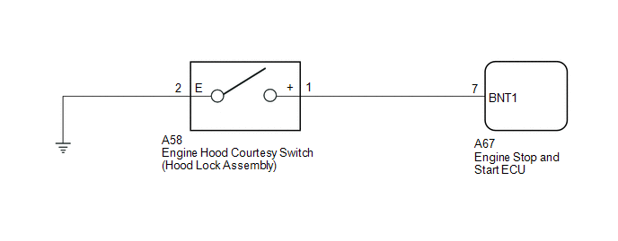
The engine stop and start ECU detects whether the engine hood is open or closed based on a signal received from the engine hood courtesy switch built into the hood lock assembly.
- The engine stop and start ECU prohibits starting of the engine by stop and start control and changes the mode to "stalled" if the engine hood is open with the clutch pedal is released while the engine is stopped by stop and start control.
WIRING DIAGRAM
CAUTION / NOTICE / HINT
For wire harness and connector inspection procedures and precautions, refer to

PROCEDURE
| 1. | READ VALUE USING GTS (HOOD COURTESY SWITCH) |
NOTICE:
Before performing this step, check that the engine hood can be opened by pulling the hood lock control cable.
Powertrain > Stop and Start > Data List| Tester Display |
|---|
| Hood Courtesy Switch |
(a) According to the display on the GTS, read the Data List.
OK:
| GTS Display | Condition | Normal Condition |
|---|---|---|
| Hood Courtesy Switch | Engine hood closed | ON |
| Engine hood open | OFF |
| OK |
 | CHECK AND ADJUST HOOD LOCK ASSEMBLY FITTING (ADJUST HOOD) |
|

| 2. | INSPECT ENGINE HOOD COURTESY SWITCH (HOOD LOCK ASSEMBLY) |
(a) Inspect the engine hood courtesy switch (hood lock assembly).
Click here

| NG |
 | REPLACE ENGINE HOOD COURTESY SWITCH (HOOD LOCK ASSEMBLY) |
|

| 3. | CHECK HARNESS AND CONNECTOR (ENGINE HOOD COURTESY SWITCH (HOOD LOCK ASSEMBLY) - BODY GROUND) |
(a) Disconnect the A58 engine hood courtesy switch (hood lock assembly) connector.
(b) Measure the resistance according to the value(s) in the table below.
Standard Resistance:
| Tester Connection | Condition | Specified Condition |
|---|---|---|
| A58-2 (E) - Body ground | Always | Below 1 Ω |
| NG |
 | REPAIR OR REPLACE HARNESS OR CONNECTOR |
|

| 4. | CHECK HARNESS AND CONNECTOR (ENGINE STOP AND START ECU - ENGINE HOOD COURTESY SWITCH (HOOD LOCK ASSEMBLY)) |
(a) Disconnect the A67 engine stop and start ECU connector.
(b) Disconnect the A58 engine hood courtesy switch (hood lock assembly) connector.
(c) Measure the resistance according to the value(s) in the table below.
Standard Resistance:
| Tester Connection | Condition | Specified Condition |
|---|---|---|
| A67-7 (BNT1) - A58-1 (+) | Always | Below 1 Ω |
| A67-7 (BNT1) - Body ground | Always | 10 kΩ or higher |
| A58-1 (+) - Body ground | Always | 10 kΩ or higher |
| OK |
 | CHECK AND ADJUST HOOD LOCK ASSEMBLY FITTING (ADJUST HOOD) |
| NG |
 | REPAIR OR REPLACE HARNESS OR CONNECTOR |
 Starter Signal Circuit
DESCRIPTION The engine stop and start ECU uses its internal starter circuit to drive the starter drive relay (ST No. 1 relay) and operate the starter. WIRING DIAGRAM
CAUTION / NOTICE / HINT
When the engine stop and start ECU is replaced, read the number of starter operations before replacement and record this number to the new engine stop and start ECU after replacement...
 Stop and Start Priority Control System
DESCRIPTION In stop and start control status, there is normal status (Standard) and stop and start priority status (Extended). Stop and start control status can be switched to the desired mode by pressing and holding the stop and start system cancel switch (combination switch assembly), or by operating the steering pad switch assembly, and the mode change is also shown on the multi-information display screen...
Other information:
Toyota Yaris XP210 (2020-2026) Owner's Manual: How to Use Aha™
Aha* 1 is an application which can be used to enjoy various Internet content such as Internet radio and podcasts. Stay connected to your friends activities by getting updates from Facebook and Twitter. Using the location-based service, nearby services and destinations can be searched or real-time local information can be obtained...
Toyota Yaris XP210 (2020-2026) Reapir and Service Manual: Removal
REMOVAL CAUTION / NOTICE / HINT The necessary procedures (adjustment, calibration, initialization, or registration) that must be performed after parts are removed, installed, or replaced during the airbag sensor assembly removal/installation are shown below...
Categories
- Manuals Home
- Toyota Yaris Owners Manual
- Toyota Yaris Service Manual
- Key Battery Replacement
- Brake System Control Module "A" System Voltage System Voltage Low (C137BA2)
- Adjustment
- New on site
- Most important about car
Break-In Period
No special break-in is necessary, but a few precautions in the first 600 miles (1,000 km) may add to the performance, economy, and life of the vehicle.
Do not race the engine. Do not maintain one constant speed, either slow or fast, for a long period of time. Do not drive constantly at full-throttle or high engine rpm for extended periods of time. Avoid unnecessary hard stops. Avoid full-throttle starts.