Toyota Yaris: Stop And Start System / Starter Signal Circuit
DESCRIPTION
The engine stop and start ECU uses its internal starter circuit to drive the starter drive relay (ST No. 1 relay) and operate the starter.
WIRING DIAGRAM
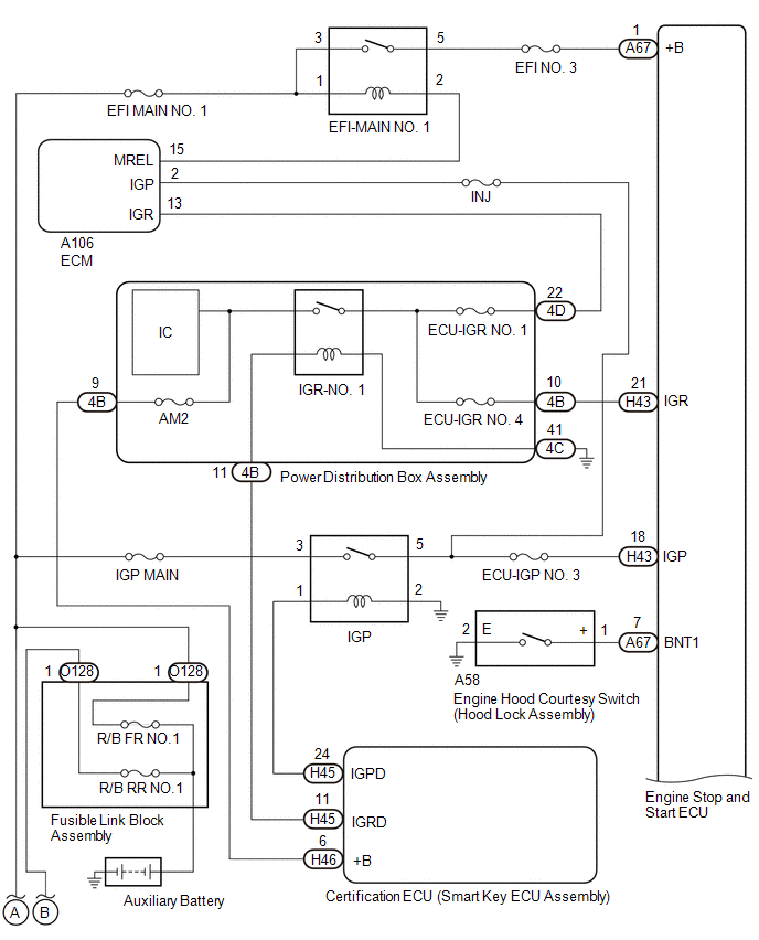
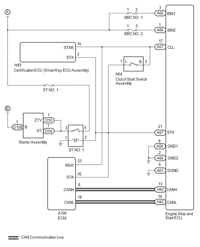
CAUTION / NOTICE / HINT
-
When the engine stop and start ECU is replaced, read the number of starter operations before replacement and record this number to the new engine stop and start ECU after replacement.
Click here

-
When the engine stop ECU has been replaced, perform external backup boost converter (Eco run vehicle converter assembly) existence learning.
Click here

-
After replacing the engine stop and start ECU or air conditioner amplifier assembly, perform initialization/learning of the air conditioner information for the engine stop and start ECU.
Click here

-
When the starter assembly is replaced, the number of starter operations stored in the engine stop and start ECU must be reset.
Click here

- When the starter assembly is replaced, "ST NO. 1 relay" must be also replaced.
- Inspect the fuses for circuits related to this system before performing the following procedure.
HINT:
For wire harness and connector inspection procedures and precautions, refer to

PROCEDURE
| 1. | CHECK CRANKING |
(a) Turn the ignition switch to ON and check that the engine cranks.
| Result | Proceed to |
|---|---|
| Engine cranks | A |
| Engine does not crank | B |
| B |
 | GO TO STEP 20 |
|

| 2. | READ VALUE USING GTS (Starter(Hood Close)) |
| Tester Display |
|---|
| Starter(Hood Close) |
(a) Check whether the engine cranks while the Active Test "Starter(Hood Close)" is being performed.
NOTICE:
The Active Test "Starter(Hood Close)" is stopped automatically 3 seconds after the starter assembly begins operating.
Standard:
Engine cranks
| NG |
 | GO TO STEP 17 |
|

| 3. | CHECK DTC OUTPUT (SFI SYSTEM) |
(a) Enter the following menus: Powertrain / Engine / Trouble Codes.
Powertrain > Engine > Trouble Codes| Result | Proceed to |
|---|---|
| SFI system DTCs are not output | A |
| SFI system DTC (poor startability detected) output, and starter does not rotate | |
| SFI system DTC (poor startability detected) output, and starter rotates | B |
| DTCs other than SFI system DTC (poor startability detected) are output |
HINT:
- According to the display on the GTS, check the freeze frame data item [Cranking Time] in the sets of freeze frame data.
- If the value of [Cranking Time] is approximately 3 seconds, the stop and start control system or starter system may be malfunctioning.
- If the value of [Cranking Time] is small (approximately 0.5 seconds or less: the minimum value varies depending on the model), the SFI system may be malfunctioning.
- The Data List item [Cranking Time] indicates the length of time starter operation is requested by the engine stop and start ECU. If the engine speed exceeds the specified value, the engine stop and start ECU cancels its start request.
| B |
 | GO TO SFI SYSTEM |
|

| 4. | CHECK FREEZE FRAME DATA |
NOTICE:
The freeze frame data is cleared when DTCs are cleared. Be sure to make a note of necessary data in advance.
HINT:
Using the time-series freeze frame data, confirm the freeze frame data recorded the moment the DTC was stored and after the DTC was stored. This information can be useful when troubleshooting.
(a) According to the prompts on the GTS screen, read the time-series freeze frame data to confirm the vehicle conditions when an engine stall occurred while stop and start control was operating.
(b) Check the freeze frame data for engine stall history and engine start failure.
| GTS Display | Result | Proceed to |
|---|---|---|
| Engine Stall History during Stop&Start (Hood Open) | Yes | A |
| Engine Stall History during Stop&Start (Collision or Battery Voltage Low) | Yes | B |
| Engine Stall History during Engine Starting (Collision) | ||
| Engine Start Fail | Yes | C |
| B |
 | GO TO STEP 9 |
| C |
 | GO TO STEP 10 |
|

| 5. | READ VALUE USING GTS (HOOD COURTESY SWITCH) |
NOTICE:
Before performing this step, check that the engine hood can be opened by pulling the hood lock control cable.
Powertrain > Stop and Start > Data List| Tester Display |
|---|
| Hood Courtesy Switch |
(a) Check the Data List when the hood is opened and closed.
OK:
| Condition | Normal Condition |
|---|---|
| Engine hood closed | ON |
| Engine hood open | OFF |
| OK |
 | USE SIMULATION METHOD TO CHECK |
|

| 6. | INSPECT ENGINE HOOD COURTESY SWITCH (HOOD LOCK ASSEMBLY) |
Click here

| NG |
 | REPLACE ENGINE HOOD COURTESY SWITCH (HOOD LOCK ASSEMBLY) |
|

| 7. | CHECK HARNESS AND CONNECTOR (ENGINE HOOD COURTESY SWITCH (HOOD LOCK ASSEMBLY) - BODY GROUND) |
(a) Disconnect the A58 engine hood courtesy switch (hood lock assembly) connector.
(b) Measure the resistance according to the value(s) in the table below.
Standard Resistance:
| Tester Connection | Condition | Specified Condition |
|---|---|---|
| A58-2 (E) - Body ground | Always | Below 1 Ω |
| NG |
 | REPAIR OR REPLACE HARNESS OR CONNECTOR |
|

| 8. | CHECK HARNESS AND CONNECTOR (ENGINE STOP AND START ECU - ENGINE HOOD COURTESY SWITCH (HOOD LOCK ASSEMBLY)) |
(a) Disconnect the A67 engine stop and start ECU connector.
(b) Disconnect the A58 engine hood courtesy switch (hood lock assembly) connector.
(c) Measure the resistance according to the value(s) in the table below.
Standard Resistance:
| Tester Connection | Condition | Specified Condition |
|---|---|---|
| A67-7 (BNT1) - A58-1 (+) | Always | Below 1 Ω |
| A67-7 (BNT1) - Body ground | Always | 10 kΩ or higher |
| A58-1 (+) - Body ground | Always | 10 kΩ or higher |
| OK |
 | REPLACE ENGINE STOP AND START ECU |
| NG |
 | REPAIR OR REPLACE HARNESS OR CONNECTOR |
| 9. | CHECK VEHICLE CONDITION (COLLISION HISTORY) |
(a) Check if the vehicle was in a collision when the engine stalled.
| Result | Proceed to |
|---|---|
| Vehicle was in collision when engine stalled | A |
| Vehicle was not in collision when engine stalled | B |
HINT:
When "Engine Stall History during Stop & Start (Collision or Battery Voltage Low)" or "Engine Stall History during Engine Starting (Collision)" is stored: This may have been stored because the vehicle was in a collision or a collision detection signal was input while stop and start control was operating.
| A |
 | END (ENGINE STALLED BECAUSE COLLISION DETECTION SIGNAL WAS RECEIVED) |
| B |
 | GO TO AIRBAG SYSTEM |
| 10. | CHECK HARNESS AND CONNECTOR (ENGINE STOP AND START ECU - ST NO. 1 RELAY) |
(a) Disconnect the H45 certification ECU (smart key ECU assembly) connector.
(b) Disconnect the A64 clutch start switch assembly connector.
(c) Disconnect the A106 ECM connector.
(d) Disconnect the A67 engine stop and start ECU connector.
(e) Remove the ST NO. 1 relay from the No. 1 engine room relay block.
(f) Measure the resistance according to the value(s) in the table below.
Standard Resistance:
| Tester Connection | Condition | Specified Condition |
|---|---|---|
| H45-3 (STA) - 2 (ST NO. 1 relay holder) | Always | Below 1 Ω |
| H45-3 (STA) - Body ground | Always | 10 kΩ or higher |
| 2 (ST NO. 1 relay holder) - Body ground | Always | 10 kΩ or higher |
| NG |
 | REPAIR OR REPLACE HARNESS OR CONNECTOR |
|

| 11. | CHECK HARNESS AND CONNECTOR (ST NO. 1 RELAY - BODY GROUND) |
(a) Remove the ST NO. 1 relay from the No. 1 engine room relay block.
(b) Measure the resistance according to the value(s) in the table below.
Standard Resistance:
| Tester Connection | Condition | Specified Condition |
|---|---|---|
| 1 (ST NO. 1 relay holder) - Body ground | Always | Below 1 Ω |
| NG |
 | REPAIR OR REPLACE HARNESS OR CONNECTOR |
|

| 12. | CHECK HARNESS AND CONNECTOR (ST NO. 1 RELAY - BATTERY) |
| (a) Remove the ST NO. 1 relay from the No. 1 engine room relay block. |
|
(b) Measure the resistance according to the value(s) in the table below.
Standard Resistance:
| Tester Connection | Condition | Specified Condition |
|---|---|---|
| 5 (ST NO. 1 relay holder) - Body ground | Always | 9.5 to 14 V |
| NG |
 | REPAIR OR REPLACE HARNESS OR CONNECTOR |
|

| 13. | CHECK HARNESS AND CONNECTOR (STARTER ASSEMBLY - BATTERY) |
| (a) Measure the resistance according to the value(s) in the table below. Standard Resistance:
CAUTION: Before performing this step, check that the starter assembly connector F1 is not disconnected or loose. |
|
| NG |
 | REPAIR OR REPLACE HARNESS OR CONNECTOR |
|

| 14. | CHECK HARNESS AND CONNECTOR (ST NO. 1 RELAY - STARTER ASSEMBLY) |
(a) Remove the ST NO. 1 relay from the No. 1 engine room relay block.
(b) Disconnect the D54 starter assembly connectors.
(c) Measure the resistance according to the value(s) in the table below.
Standard Resistance:
| Tester Connection | Condition | Specified Condition |
|---|---|---|
| 3 (ST NO. 1 relay holder) - D54-1 (ST) | Always | Below 1 Ω |
| 3 (ST NO. 1 relay holder) - D55-1 (ZYV) | Always | Below 1 Ω |
| NG |
 | REPAIR OR REPLACE HARNESS OR CONNECTOR |
|

| 15. | INSPECT RELAY (ST NO. 1 RELAY) |
Click here

| NG |
 | REPAIR OR REPLACE HARNESS OR CONNECTOR |
|

| 16. | INSPECT STARTER ASSEMBLY |
Click here

| OK |
 | REPLACE ENGINE STOP AND START ECU |
| NG |
 | REPLACE STARTER ASSEMBLY |
| 17. | CHECK HARNESS AND CONNECTOR (POWER SUPPLY CIRCUIT) |
(a) Disconnect the A66, A67 and H43 engine stop and start ECU connectors.

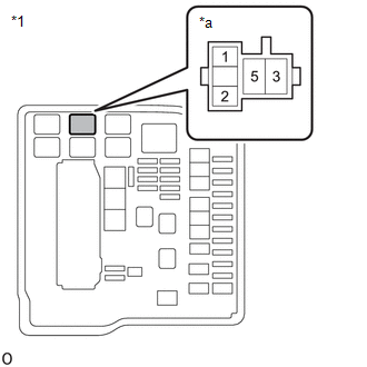
| *a | Front view of wire harness connector (to Engine Stop and Start ECU) | - | - |
(b) Measure the resistance according to the value(s) in the table below.
Standard Resistance:
| Tester Connection | Condition | Specified Condition |
|---|---|---|
| A66-3 (BIN1) - Body ground | Always | 9.5 to 14 V |
| A66-1 (BIN2) - Body ground | Always | 9.5 to 14 V |
(c) Turn the ignition switch to ON.
(d) Measure the voltage according to the value(s) in the table below.
Standard Resistance:
| Tester Connection | Switch Condition | Specified Condition |
|---|---|---|
| A67-1 (+B) - Body ground | Ignition switch ON | 9.5 to 14 V |
| H43-18 (IGP) - Body ground | Ignition switch ON | 9.5 to 14 V |
| H43-21 (IGR) - Body ground | Ignition switch ON | 9.5 to 14 V |
| NG |
 | REPAIR OR REPLACE HARNESS OR CONNECTOR |
|

| 18. | CHECK HARNESS AND CONNECTOR (ENGINE STOP AND START ECU - BODY GROUND) |
(a) Disconnect the A66 and A67 engine stop and start ECU connectors.
(b) Measure the voltage according to the value(s) in the table below.
Standard Resistance:
| Tester Connection | Condition | Specified Condition |
|---|---|---|
| A66-2 (GND2) - Body ground | Always | Below 1 Ω |
| A67-6 (DGND) - Body ground | Always | Below 1 Ω |
| A66-8 (GND1) - Body ground | Always | Below 1 Ω |
| NG |
 | REPAIR OR REPLACE HARNESS OR CONNECTOR |
|

| 19. | CHECK HARNESS AND CONNECTOR (ENGINE STOP AND START ECU - ST NO. 1 RELAY) |
(a) Disconnect the H45 certification ECU (smart key ECU assembly) connector.
(b) Disconnect the A64 clutch start switch assembly connector.
(c) Disconnect the A106 ECM connector.
(d) Disconnect the A67 engine stop and start ECU connector.
(e) Remove the ST NO. 1 relay from the No. 2 engine room relay block.
(f) Measure the resistance according to the value(s) in the table below.
Standard Resistance:
| Tester Connection | Condition | Specified Condition |
|---|---|---|
| A67-21 (STA) - 2 (ST NO. 1 relay holder) | Always | Below 1 Ω |
| A67-21 (STA) - Body ground | Always | 10 kΩ or higher |
| 2 (ST NO. 1 relay holder) - Body ground | Always | 10 kΩ or higher |
| OK |
 | REPLACE ENGINE STOP AND START ECU |
| NG |
 | REPAIR OR REPLACE HARNESS OR CONNECTOR |
| 20. | READ VALUE USING GTS (Starter(Hood Close)) |
(a) Enter the following menus: Powertrain / Stop and Start / Active Test / Starter(Hood Close)
Powertrain > Stop and Start > Active Test| Tester Display |
|---|
| Starter(Hood Close) |
(b) Check whether the engine cranks while the Active Test "Starter(Hood Close)" is being performed.
NOTICE:
The Active Test "Starter(Hood Close)" is stopped automatically 3 seconds after the starter assembly begins operating.
Standard:
Engine cranks
| Result | Proceed to |
|---|---|
| Engine cranks | A |
| Engine does not crank | B |
| B |
 | GO TO STEP 26 |
|

| 21. | READ VALUE USING GTS (NEUTRAL SWITCH) |
| Tester Display |
|---|
| Neutral Switch |
(a) Depress the clutch pedal and read the values displayed on the GTS.
| Tester Display | Result | Proceed to |
|---|---|---|
| Clutch Lower Switch | Fully Depressed | ON |
| Clutch Lower Switch | Fully Released | OFF |
| NG |
 | GO TO STEP 24 |
|

| 22. | INSPECT CLUTCH START SWITCH ASSEMBLY |
Click here

| NG |
 | REPLACE CLUTCH START SWITCH ASSEMBLY |
|

| 23. | CHECK HARNESS AND CONNECTOR (CERTIFICATION ECU (SMART KEY ECU ASSEMBLY) - ST NO. 1 RELAY) |
(a) Disconnect the H45 certification ECU (smart key ECU assembly) connector.
(b) Remove the ST NO. 1 relay from the No. 1 engine room relay block.
(c) Measure the resistance according to the value(s) in the table below.
Standard Resistance:
| Tester Connection | Condition | Specified Condition |
|---|---|---|
| H45-3 (STA) - 2 (ST NO. 1 relay holder) | Shift lever in P or N | Below 1 Ω |
| H45-3 (STA) - Body ground | Shift lever not in P or N | 10 kΩ or higher |
| OK |
 | PROCEED TO NEXT SUSPECTED AREA SHOWN IN PROBLEM SYMPTOMS TABLE |
| NG |
 | REPAIR OR REPLACE HARNESS OR CONNECTOR |
| 24. | CHECK HARNESS AND CONNECTOR (CERTIFICATION ECU (SMART KEY ECU ASSEMBLY) - CLUTCH START SWITCH ASSEMBLY) |
(a) Disconnect the A64 clutch start switch assembly connector.
(b) Disconnect the H45 certification ECU (smart key ECU assembly) connector.
(c) Disconnect the A67 engine stop and start ECU connector.
(d) Measure the resistance according to the value(s) in the table below.
Standard Resistance:
| Tester Connection | Condition | Specified Condition |
|---|---|---|
| H45-10 (STAR) - A67-17 (CLL) | Always | Below 1 Ω |
| H45-10 (STAR) - A64-2 (B) | Always | Below 1 Ω |
| H45-10 (STAR) - Body ground | Always | 10 kΩ or higher |
| A67-17 (CLL) - Body ground | Always | 10 kΩ or higher |
| A64-2 (B) - Body ground | Always | 10 kΩ or higher |
| NG |
 | REPAIR OR REPLACE HARNESS OR CONNECTOR |
|

| 25. | CHECK CERTIFICATION ECU (SMART KEY ECU ASSEMBLY) (STAR SIGNAL) |
(a) Disconnect A67 the engine stop and start ECU connector.
(b) Measure the voltage according to the value(s) in the table below.
Standard Voltage:
| Tester Connection | Switch Condition | Specified Condition |
|---|---|---|
| A67-17 (CLL) - Body ground | Engine started using push start switch assembly (engine start) | 9.5 to 14 V |
| OK |
 | PROCEED TO NEXT SUSPECTED AREA SHOWN IN PROBLEM SYMPTOMS TABLE |
| NG |
 | GO TO ENTRY AND START SYSTEM (START FUNCTION) |
| 26. | CHECK HARNESS AND CONNECTOR (STA SIGNAL) |
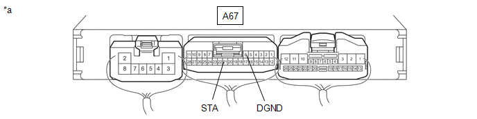
| *a | Front view of wire harness connector (to Engine Stop and Start ECU) | - | - |
(a) Measure the resistance according to the value(s) in the table below.
(b) Check the waveform immediately after starting.
Standard Resistance:
| Tester Connection | Condition | Specified Condition |
|---|---|---|
| A67-21 (STA) - A67-6 (DGND) | Ignition switch ON | 6 to 14 V |
| Cranking commanded via Active Test item Starter(Hood Close)*1 |
- *1: In the case of stop and start inspection procedure.
| Result | Proceed to |
|---|---|
| OK | A |
| NG | B |
| NG*1 | C |
- *1: In the case of stop and start inspection procedure.
| B |
 | GO TO STEP 37 |
| C |
 | GO TO PROBLEM SYMPTOMS TABLE (ENGINE DOS NOT START) |
|

| 27. | INSPECT RELAY (ST NO. 1 RELAY) |
Click here

| NG |
 | REPLACE RELAY (ST NO. 1 RELAY) |
|

| 28. | CHECK HARNESS AND CONNECTOR (ST NO. 1 RELAY - BATTERY) |
| (a) Remove the ST NO. 1 relay from the No. 1 engine room relay block. |
|

(b) Measure the voltage according to the value(s) in the table below.
Standard Resistance:
| Tester Connection | Switch Condition | Specified Condition |
|---|---|---|
| 5 (ST NO. 1 relay holder) - Body ground | Always | 9.5 to 14 V |
| NG |
 | REPAIR OR REPLACE HARNESS OR CONNECTOR |
|

| 29. | CHECK HARNESS AND CONNECTOR (ST NO. 1 RELAY - STARTER ASSEMBLY) |
(a) Remove the ST NO. 1 relay from the No. 1 engine room relay block.
(b) Disconnect the starter assembly connector.
(c) Measure the voltage according to the value(s) in the table below.
Standard Resistance:
| Tester Connection | Condition | Specified Condition |
|---|---|---|
| 3 (ST NO. 1 relay holder) - D54-1 (ST) | Always | Below 1 Ω |
| 3 (ST NO. 1 relay holder) - D55-1 (ZYV) | Always | Below 1 Ω |
| NG |
 | REPAIR OR REPLACE HARNESS OR CONNECTOR |
|

| 30. | CHECK HARNESS AND CONNECTOR (ST NO. 1 RELAY - BODY GROUND) |
(a) Remove the ST NO. 1 relay from the No. 1 engine room relay block.
(b) Measure the resistance according to the value(s) in the table below.
Standard Resistance:
| Tester Connection | Condition | Specified Condition |
|---|---|---|
| 1 (ST NO. 1 relay holder) - Body ground | Always | Below 1 Ω |
| NG |
 | REPAIR OR REPLACE HARNESS OR CONNECTOR |
|

| 31. | CHECK HARNESS AND CONNECTOR (ENGINE STOP AND START ECU - ST NO. 1 RELAY) |
(a) Disconnect the H45 certification ECU (smart key ECU assembly) connector.
(b) Disconnect the A64 clutch switch assembly connector.
(c) Disconnect the A106 ECM connector.
(d) Disconnect the A67 engine stop and start ECU connector.
(e) Remove the ST NO. 1 relay from the No. 2 engine room relay block.
(f) Measure the resistance according to the value(s) in the table below.
Standard Resistance:
| Tester Connection | Condition | Specified Condition |
|---|---|---|
| A67-21 (STA) - 2 (ST NO. 1 relay holder) | Always | Below 1 Ω |
| A67-21 (STA) - Body ground | Always | 10 kΩ or higher |
| 2 (ST NO. 1 relay holder) - Body ground | Always | 10 kΩ or higher |
| NG |
 | REPAIR OR REPLACE HARNESS OR CONNECTOR |
|

| 32. | CHECK STARTER SIGNAL (OUTPUT WAVEFORM) |
(a) Connect the positive (+) lead of an oscilloscope to the positive (+) battery terminal and the negative (-) lead to the negative (-) battery terminal.
(b) While cranking the engine, count the number of times the waveform drops.
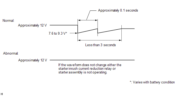
Standard:
Waveform drops 2 times
| Number of Times Waveform Dropped | Proceed to |
|---|---|
| 0 times | A |
| 2 times | B |
| B |
 | GO TO STEP 36 |
|

| 33. | INSPECT STARTER INRUSH CURRENT REDUCTION RELAY |
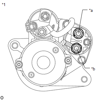
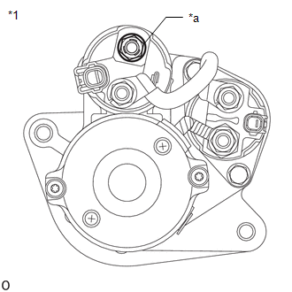
| *1 | Starter Assembly |
| *a | B Terminal |
| *b | M Terminal |
(a) Disconnect the cable from the negative (-) battery terminal.
(b) Disconnect terminals B and M of the starter inrush current reduction relay.
(c) Measure the resistance according to the value(s) in the table below.
Standard Resistance:
| Tester Connection | Condition | Specified Condition |
|---|---|---|
| B Terminal - M Terminal | Always | Below 1 Ω |
| NG |
 | GO TO STEP 35 |
|

| 34. | INSPECT STARTER ASSEMBLY (C TERMINAL) |
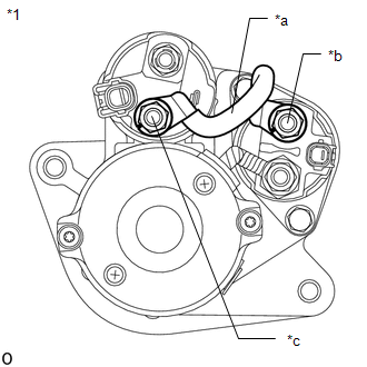
| *1 | Starter Assembly |
| *a | Inspect Part |
| *b | B Terminal |
| *c | C Terminal |
(a) Disconnect the cable from the negative (-) battery terminal.
(b) Disconnect terminal B of the starter inrush current reduction relay.
(c) Disconnect terminal C of the starter assembly.
(d) Measure the resistance according to the value(s) in the table below.
Standard Resistance:
| Tester Connection | Condition | Specified Condition |
|---|---|---|
| C Terminal - B Terminal | Always | Below 1 Ω |
| OK |
 | REPLACE STARTER ASSEMBLY |
| NG |
 | REPAIR OR REPLACE WIRE HARNESS |
| 35. | INSPECT STARTER ASSEMBLY (M TERMINAL) |
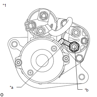
| *1 | Starter Assembly |
| *a | Inspect Part |
| *b | M Terminal |
(a) Disconnect the cable from the negative (-) battery terminal.
(b) Disconnect terminal M of the starter inrush current reduction relay.
(c) Measure the resistance according to the value(s) in the table below.
Standard Resistance:
| Tester Connection | Condition | Specified Condition |
|---|---|---|
| M Terminal - Body ground | Always | Below 1 Ω |
| OK |
 | REPLACE STARTER INRUSH CURRENT REDUCTION RELAY |
| NG |
 | REPLACE STARTER ASSEMBLY |
| 36. | INSPECT STARTER ASSEMBLY |
Click here

| OK |
 | USE SIMULATION METHOD TO CHECK |
| NG |
 | REPLACE STARTER ASSEMBLY |
| 37. | CHECK HARNESS AND CONNECTOR (POWER SUPPLY CIRCUIT) |
(a) Disconnect the A66, A67 and H43 engine stop and start ECU connectors.
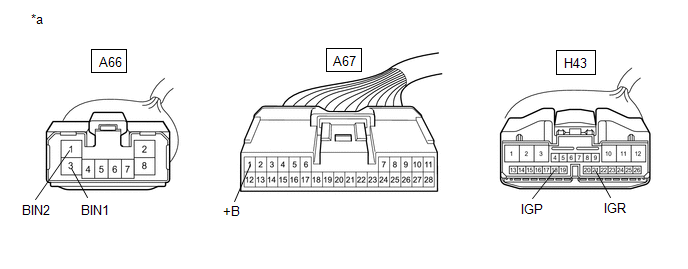
| *a | Front view of wire harness connector (to Engine Stop and Start ECU) | - | - |
(b) Measure the resistance according to the value(s) in the table below.
Standard Resistance:
| Tester Connection | Condition | Specified Condition |
|---|---|---|
| A66-3 (BIN1) - Body ground | Always | 9.5 to 14 V |
| A66-1 (BIN2) - Body ground | Always | 9.5 to 14 V |
(c) Turn the ignition switch to ON.
(d) Measure the voltage according to the value(s) in the table below.
Standard Resistance:
| Tester Connection | Switch Condition | Specified Condition |
|---|---|---|
| A67-1 (+B) - Body ground | Ignition switch ON | 9.5 to 14 V |
| H43-18 (IGP) - Body ground | Ignition switch ON | 9.5 to 14 V |
| H43-21 (IGR) - Body ground | Ignition switch ON | 9.5 to 14 V |
| NG |
 | REPAIR OR REPLACE HARNESS OR CONNECTOR |
|

| 38. | CHECK HARNESS AND CONNECTOR (ENGINE STOP AND START ECU - BODY GROUND) |
(a) Disconnect the A66 and A67 engine stop and start ECU connectors.
(b) Measure the voltage according to the value(s) in the table below.
Standard Resistance:
| Tester Connection | Condition | Specified Condition |
|---|---|---|
| A66-2 (GND2) - Body ground | Always | Below 1 Ω |
| A67-6 (DGND) - Body ground | Always | Below 1 Ω |
| A66-8 (GND1) - Body ground | Always | Below 1 Ω |
| OK |
 | REPLACE ENGINE STOP AND START ECU |
| NG |
 | REPAIR OR REPLACE HARNESS OR CONNECTOR |
 Lost Communication with ECM/PCM "A" Missing Message (U010087,U012687,U012987,U013187,U014087,U015187,U015587,U016487,U117087)
DESCRIPTION The engine stop and start ECU communicates with the SFI system, electronically controlled brake system, power steering system, air conditioning system, airbag system and main body ECU (multiplex network body ECU) via CAN communication...
 Engine Hood Courtesy Switch Circuit
DESCRIPTION The engine stop and start ECU detects whether the engine hood is open or closed based on a signal received from the engine hood courtesy switch built into the hood lock assembly...
Other information:
Toyota Yaris XP210 (2020-2026) Reapir and Service Manual: Installation
I..
Toyota Yaris XP210 (2020-2026) Reapir and Service Manual: Removal
REMOVAL CAUTION / NOTICE / HINT The necessary procedures (adjustment, calibration, initialization or registration) that must be performed after parts are removed and installed, or replaced during fuel injector assembly removal/installation are shown below...
Categories
- Manuals Home
- Toyota Yaris Owners Manual
- Toyota Yaris Service Manual
- Battery Monitor Module General Electrical Failure (P058A01)
- Power Integration No.1 System Missing Message (B235287,B235587,B235787-B235987)
- Opening and Closing the Liftgate/Trunk Lid
- New on site
- Most important about car
Fuel Gauge
The fuel gauge shows approximately how much fuel is remaining in the tank when the ignition is switched ON. We recommend keeping the tank over 1/4 full.
