Toyota Yaris: Can Communication System / Center Airbag Sensor Communication Stop Mode

Toyota Yaris XP210 (2020-2024) Reapir and Service Manual / Power Source & Network / Networking / Can Communication System / Center Airbag Sensor Communication Stop Mode

DESCRIPTION

Detection Item

Symptom

Trouble Area

Center Airbag Sensor Communication Stop Mode

Communication stop for "Airbag" is indicated on the "Communication Bus Check" screen of the GTS.

Click here

  • Airbag sensor assembly main line or connector
  • Power source circuit of airbag sensor assembly
  • Airbag sensor assembly ground circuit
  • Airbag sensor assembly

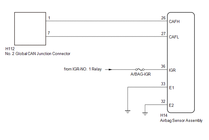
WIRING DIAGRAM

CAUTION / NOTICE / HINT

CAUTION:

When performing the confirmation driving pattern, obey all speed limits and traffic laws.

NOTICE:

  • Because the order of diagnosis is important to allow correct diagnosis, make sure to begin troubleshooting using How to Proceed with Troubleshooting when CAN communication system related DTCs are output.

    Click here

  • Before measuring the resistance of the CAN bus, turn the ignition switch off and leave the vehicle for 1 minute or more without operating the key or any switches, or opening or closing the doors. After that, disconnect the cable from the negative (-) auxiliary battery terminal and leave the vehicle for 1 minute or more before measuring the resistance.
  • After the ignition switch is turned off, there may be a waiting time before disconnecting the negative (-) auxiliary battery terminal.

    Click here

  • When disconnecting and reconnecting the auxiliary battery, there is an automatic learning function that completes learning when the respective system is used.

    Click here

  • Some parts must be initialized and set when replacing or removing and installing parts.

    Click here

  • After performing repairs, perform the DTC check procedure and confirm that the DTCs are not output again.

    DTC check procedure: Turn the ignition switch to ON and wait for 1 minute or more. Then operate the suspected malfunctioning system and drive the vehicle at 60 km/h (37 mph) or more for 5 minutes or more.

  • After the repair, perform the CAN bus check and check that all the ECUs and sensors connected to the CAN communication system are displayed as normal.

    Click here

  • Inspect the fuses for circuits related to this system before performing the following procedure.

HINT:

  • Before disconnecting related connectors for inspection, push in on each connector body to check that the connector is not loose or disconnected.
  • When a connector is disconnected, check that the terminals and connector body are not cracked, deformed or corroded.

PROCEDURE

1.

CHECK FOR OPEN IN CAN BUS LINES (AIRBAG SENSOR ASSEMBLY BRANCH LINE)

(a) Disconnect the cable from the negative (-) auxiliary battery terminal.

(b) Disconnect the airbag sensor assembly connector.

(c) Measure the resistance according to the value(s) in the table below.

Standard Resistance:

Tester Connection

Condition

Specified Condition

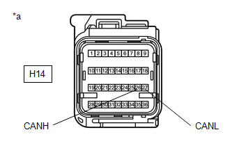
H14-26 (CAFH) - H14-27 (CAFL)

Cable disconnected from negative (-) auxiliary battery terminal

54 to 69 Ω

*a

Front view of wire harness connector

(to Airbag Sensor Assembly)

NG

REPAIR OR REPLACE CAN BRANCH LINES OR CONNECTOR (AIRBAG SENSOR ASSEMBLY)

OK

2.

CHECK HARNESS AND CONNECTOR (POWER SOURCE CIRCUIT)

(a) Measure the resistance according to the value(s) in the table below.

Standard Resistance:

Tester Connection

Condition

Specified Condition

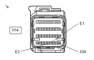
H14-32 (E2) - Body ground

Cable disconnected from negative (-) auxiliary battery terminal

Below 1 Ω

H14-33 (E1) - Body ground

Cable disconnected from negative (-) auxiliary battery terminal

Below 1 Ω

*a

Front view of wire harness connector

(to Airbag Sensor Assembly)

(b) Reconnect the cable to the negative (-) auxiliary battery terminal.

(c) Measure the voltage according to the value(s) in the table below.

Standard Voltage:

Tester Connection

Condition

Specified Condition

H14-36 (IGR) - Body ground

Ignition switch ON

11 to 14 V

OK

REPLACE AIRBAG SENSOR ASSEMBLY

NG

REPAIR OR REPLACE HARNESS OR CONNECTOR (POWER SOURCE CIRCUIT)

    Certification ECU Communication Stop Mode

    DESCRIPTION Detection Item Symptom Trouble Area Certification ECU Communication Stop Mode Communication stop for "Certification (Smart) and/or Power Management" is indicated on the "Communication Bus Check" screen of the GTS...

    Engine Stop and Start ECU Communication Stop Mode

    DESCRIPTION Detection Item Symptom Trouble Area Engine Stop and Start ECU Communication Stop Mode Communication stop for "Stop and Go/Start" is indicated on the "Communication Bus Check" screen of the GTS...

    Other information:

    Toyota Yaris XP210 (2020-2024) Reapir and Service Manual: Diagnostic Trouble Code Chart


    DIAGNOSTIC TROUBLE CODE CHART SFI System DTC No. Detection Item MIL Note Link P001013 A Camshaft Position Actuator Bank 1 Circuit Open Comes on SAE: P0010 P001100 Camshaft Position "A" - Timing Over-Advanced or System Performance Bank 1 Comes on SAE: P0011 P001200 Camshaft Position "A" - Timing Over-Retarded Bank 1 Comes on SAE: P0012 P001313 Camshaft Position "B" - Actuator Bank 1 Circuit Open Comes on SAE: P0013 P001400 Camshaft Position "B" - Timing Over-Advanced or System Performance Bank 1 Comes on SAE: P0014 P001500 Camshaft Position "B" - Timing Over-Retarded Bank 1 Comes on SAE: P0015 P001600 Crankshaft Position - Camshaft Position Correlation Bank 1 Sensor A Comes on SAE: P0016 P001700 Crankshaft Position - Camshaft Position Correlation Bank 1 Sensor B Comes on SAE: P0017 P003012 HO2S Heater Control Bank 1 Sensor 1 Circuit Short to Battery Comes on SAE: P0032 P003013 HO2S Heater Control Bank 1 Sensor 1 Circuit Open Comes on SAE: P0031 P003312 Turbocharger / Supercharger Bypass Valve "A" Control Circuit Short to Battery - SAE: P0035 P003314 Turbocharger / Supercharger Bypass Valve "A" Control Circuit Short to Ground or Open - SAE: P0034 P003612 HO2S Heater Control Circuit Bank 1 Sensor 2 Circuit Short to Battery Comes on SAE: P0038 P003613 A/F (O2) Heater Control Circuit Bank 1 Sensor 2 Circuit Open Comes on SAE: P0037 P006D62 Barometric Pressure - Turbocharger/Supercharger Inlet Pressure Correlation Bank 1 Signal Compare Failure - SAE: P006D P007A11 Charge Air Cooler Temperature Sensor Bank 1 Circuit Short to Ground - SAE: P007C P007A15 Charge Air Cooler Temperature Sensor Bank 1 Circuit Short to Battery or Open - SAE: P007D P008700 Fuel Rail / System Pressure - Too Low Comes on SAE: P0087 P008800 Fuel Rail / System Pressure - Too High Comes on SAE: P0088 P008A00 Low Pressure Fuel System Pressure - Too Low - SAE: P008A P008B00 Low Pressure Fuel System Pressure - Too High - SAE: P008B P00CF62 Barometric Pressure - Turbocharger / Supercharger Boost Sensor "A" Signal Compare Failure Comes on SAE: P00CF P010012 Mass or Volume Air Flow Sensor "A" Circuit Short to Battery Comes on SAE: P0103 P010014 Mass or Volume Air Flow Sensor "A" Circuit Short to Ground or Open Comes on SAE: P0102 P010511 Manifold Absolute Pressure / Barometric Pressure Sensor Circuit Short to Ground Comes on SAE: P0107 P010515 Manifold Absolute Pressure / Barometric Pressure Sensor Circuit Short to Battery or Open Comes on SAE: P0108 P011011 Intake Air Temperature Sensor 1 Bank 1 Circuit Short to Ground Comes on SAE: P0112 P011015 Intake Air Temperature Sensor 1 Bank 1 Circuit Short to Battery or Open Comes on SAE: P0113 P011511 Engine Coolant Temperature Sensor 1 Circuit Short to Ground Comes on SAE: P0117 P011515 Engine Coolant Temperature Sensor 1 Circuit Short to Battery or Open Comes on SAE: P0118 P01152A Engine Coolant Temperature Sensor 1 Signal Stuck in Range Comes on SAE: P0116 P012011 Throttle / Pedal Position Sensor / Switch "A" Circuit Short to Ground Comes on SAE: P0122 P012015 Throttle / Pedal Position Sensor / Switch "A" Circuit Short to Battery or Open Comes on SAE: P0123 P01201C Throttle / Pedal Position Sensor / Switch "A" Circuit Voltage Out of Range Comes on SAE: P0121 P012A11 Turbocharger/Supercharger Inlet Pressure Sensor "A" Circuit Low Circuit Short to Ground - SAE: P012C P012A15 Turbocharger/Supercharger Inlet Pressure Sensor "A" Circuit High Circuit Short to Battery or Open - SAE: P012D P013616 A/F (O2) Sensor Circuit Bank 1 Sensor 2 Circuit Current (Voltage) Below Threshold Comes on SAE: P0136 P017100 System Too Lean Bank 1 Comes on SAE: P0171 P017200 System Too Rich Bank 1 Comes on SAE: P0172 P019011 Fuel Rail Pressure Sensor "A" Circuit Short to Ground Comes on SAE: P0192 P019015 Fuel Rail Pressure Sensor "A" Circuit Short to Battery or Open Comes on SAE: P0193 P019511 Engine Oil Temperature Sensor Circuit Short to Ground - SAE: P0197 P019515 Engine Oil Temperature Sensor Circuit Short to Battery or Open - SAE: P0198 P020113 Cylinder 1 Injector "A" Circuit Open Comes on SAE: P0201 P020213 Cylinder 2 Injector "A" Circuit Open Comes on SAE: P0202 P020313 Cylinder 3 Injector "A" Circuit Open Comes on SAE: P0203 P022011 Throttle/Pedal Position Sensor/Switch "B" Circuit Short to Ground Comes on SAE: P0222 P022015 Throttle/Pedal Position Sensor/Switch "B" Circuit Short to Battery or Open Comes on SAE: P0223 P023400 Turbocharger/Supercharger "A" Overboost Condition - SAE: P0234 P023511 Turbocharger/Supercharger Boost Sensor "A" Circuit Short to Ground Comes on SAE: P0237 P023515 Turbocharger/Supercharger Boost Sensor "A" Circuit Short to Battery or Open Comes on SAE: P0238 P02351C Turbocharger/Supercharger Boost Sensor "A" Circuit Voltage Out of Range - SAE: P0236 P024313 Turbocharger/Supercharger Wastegate Solenoid "A" Circuit Open Does not come on SAE: P0243 P030000 Random/Multiple Cylinder Misfire Detected Comes on/Blinks* *: The MIL flashes when a catalyst-damaging misfire is detected...

    Toyota Yaris XP210 (2020-2024) Reapir and Service Manual: Ambient Illumination Light Circuit


    DESCRIPTION The main body ECU (multiplex network body ECU) controls the operation of the following lights: Front Door Ambient Illumination Light Front Door Ambient Illumination Light LH (Front Door Trim Board Sub-assembly LH) Front Door Ambient Illumination Light RH (Front Door Trim Board Sub-assembly RH) WIRING DIAGRAM CAUTION / NOTICE / HINT NOTICE: Inspect the fuses for circuits related to this system before performing the following procedure...

    Categories

    Turning the Engine Off

    Stop the vehicle completely. Manual transaxle: Shift into neutral and set the parking brake.

    Automatic transaxle: Shift the selector lever to the P position and set the parking brake.

    Press the push button start to turn off the engine. The ignition position is off.

    read more

     
    Copyright © 2024 www.toyaris4.com