Toyota Yaris: Steering Column Assembly / Removal
REMOVAL
CAUTION / NOTICE / HINT
The necessary procedures (adjustment, calibration, initialization, or registration) that must be performed after parts are removed and installed, or replaced during the electric power steering column sub-assembly removal/installation are shown below.
Necessary Procedures After Parts Removed/Installed/Replaced| Replaced Part or Performed Procedure | Necessary Procedure | Effect/Inoperative Function when Necessary Procedure not Performed | Link |
|---|---|---|---|
| Electric power steering column sub-assembly | Assist map writing | There is a difference in steering effort between turning left and right. |
|
| Steering lock ECU (Steering lock actuator or upper bracket assembly) | Code registration |
|
|


HINT:
When the cable is disconnected/reconnected to the auxiliary battery terminal, systems temporarily stop operating. However, each system has a function that completes learning the first time the system is used.
-
Learning completes when vehicle is driven
Effect/Inoperative Function When Necessary Procedures are not Performed
Necessary Procedures
Link
Lane tracing assist system
Drive the vehicle straight ahead at 35 km/h (22 mph) or more for 5 second or more.

Pre-collision system
Stop and start system
Drive the vehicle until stop and start control is permitted (approximately 5 to 60 minutes)

-
Learning completes when vehicle is operated normally
Effect/Inoperative Function When Necessary Procedures are not Performed
Necessary Procedures
Link
Power door lock control system
- Back door opener
Perform door unlock operation with door control switch or electrical key transmitter sub-assembly switch.

Air conditioning system
After the ignition switch is turned to ON, the servo motor standard position is recognized.
-
PROCEDURE
1. PRECAUTION
Click here

2. ALIGN FRONT WHEELS FACING STRAIGHT AHEAD
3. REMOVE HORN BUTTON ASSEMBLY
Click here

4. REMOVE STEERING WHEEL ASSEMBLY
Click here

5. REMOVE LOWER STEERING COLUMN COVER
NOTICE:
Removing the lower steering column cover in the incorrect order will cause the parts to break.
(a) Release the tilt and telescopic lever and fully extend and lower the steering column assembly.
(b) Lock the tilt and telescopic lever.
| (c) Remove the 3 screws. |
|
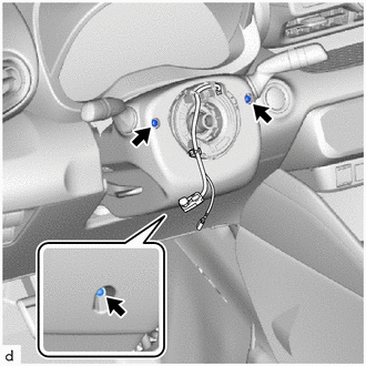
 | Push |
 | Push Area |
(d) While pressing the push area shown in the illustration to disengage the claws, slightly lower the lower steering column cover.
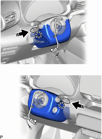
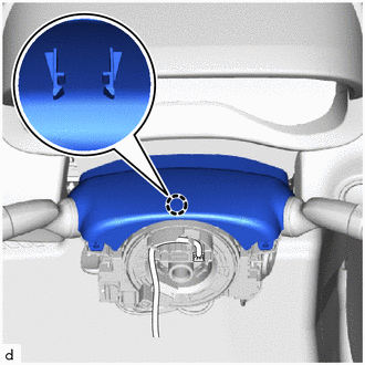
6. REMOVE UPPER STEERING COLUMN COVER
| (a) Disengage the claw to remove the upper steering column cover. |
|
7. REMOVE TURN SIGNAL SWITCH ASSEMBLY WITH SPIRAL CABLE SUB-ASSEMBLY
NOTICE:
- Do not replace the spiral cable sub-assembly and steering sensor with the auxiliary battery connected and the ignition switch ON.
- Do not rotate the spiral cable sub-assembly without the steering wheel assembly installed, with the auxiliary battery connected and the ignition switch ON.
- Ensure that the steering wheel assembly is installed and aligned straight when inspecting the steering sensor.
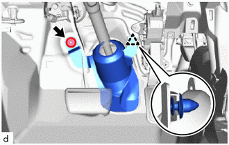
(a) Disconnect each connector from the turn signal switch assembly with spiral cable sub-assembly.
(b) Using pliers, expand the clamp.
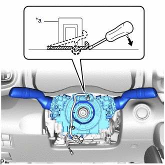
| *a | Clamp |
 | Down |
(c) While holding the clamp expanded, raise the claw using a screwdriver to disengage it, and then remove the turn signal switch assembly with spiral cable sub-assembly from the steering column assembly.
8. REMOVE CONSOLE BOX ASSEMBLY
Click here

9. REMOVE FRONT DOOR SCUFF PLATE LH
Click here

10. REMOVE COWL SIDE TRIM BOARD LH
Click here

11. REMOVE NO. 1 INSTRUMENT PANEL UNDER COVER SUB-ASSEMBLY
Click here

12. DISCONNECT FRONT DOOR OPENING TRIM WEATHERSTRIP LH
Click here

13. REMOVE NO. 1 INSTRUMENT SIDE PANEL
Click here

14. DISCONNECT HOOD LOCK CONTROL LEVER SUB-ASSEMBLY
Click here

15. REMOVE LOWER INSTRUMENT PANEL FINISH PANEL ASSEMBLY
Click here

16. REMOVE STOP LIGHT SWITCH ASSEMBLY
Click here

17. REMOVE NO. 1 AIR DUCT
Click here

18. REMOVE COLUMN HOLE COVER SILENCER SHEET
| (a) Remove the retainer. |
|
(b) Disengage the clip to remove the column hole cover silencer sheet.
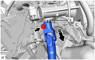
19. DISCONNECT NO. 2 STEERING INTERMEDIATE SHAFT ASSEMBLY
(a) Put matchmarks on the No. 2 steering intermediate shaft assembly and steering gear assembly.
| *a | Matchmark |
 | Disconnect in this direction |
(b) Remove the bolt.
(c) Disconnect the No. 2 steering intermediate shaft assembly from the steering gear assembly.
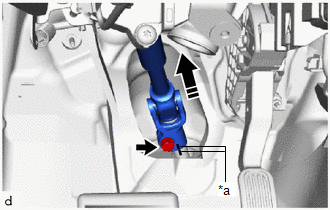
20. REMOVE NO. 2 STEERING INTERMEDIATE SHAFT ASSEMBLY
(a) Put matchmarks on the No. 2 steering intermediate shaft assembly and steering column assembly.
| *a | Matchmark |
 | Remove in this direction |
(b) Remove the bolt.
(c) Remove the No. 2 steering intermediate shaft assembly from the steering column assembly.
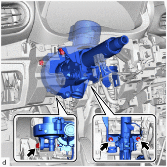
21. REMOVE STEERING COLUMN ASSEMBLY
(a) Disconnect each connector and disengage each wire harness clamp from the steering column assembly.
| (b) Remove the bolt, 2 nuts and steering column assembly. |
|
 Components
COMPONENTS ILLUSTRATION
*1 STEERING WHEEL ASSEMBLY - -
Tightening torque for "Major areas involving basic vehicle performance such as moving/turning/stopping" : N*m (kgf*cm, ft...
 Disassembly
DISASSEMBLY CAUTION / NOTICE / HINT NOTICE:
Do not drop the power steering ECU assembly, strike it with tools or subject it to impacts.
If the power steering ECU assembly is subjected to an impact, replace it with a new one...
Other information:
Toyota Yaris XP210 (2020-2026) Reapir and Service Manual: Components
COMPONENTS ILLUSTRATION *1 TURBINE OUTLET ELBOW GASKET *2 EXHAUST PIPE CLAMP *3 EXHAUST MANIFOLD CONVERTER SUB-ASSEMBLY *4 ENGINE WIRE *5 NO. 2 CLUTCH FLEXIBLE HOSE BRACKET *6 STARTER ASSEMBLY *7 FLYWHEEL HOUSING SIDE COVER *8 ENGINE ASSEMBLY WITH TRANSAXLE Tightening torque for "Major areas involving basic vehicle performance such as moving/turning/stopping": N*m (kgf*cm, ft...
Toyota Yaris XP210 (2020-2026) Reapir and Service Manual: Inspection
INSPECTION PROCEDURE 1. INSPECT NO. 1 OUTPUT SHAFT (a) Check the No. 1 output shaft for wear and damage. (b) Using a dial indicator, check the No. 1 output shaft runout. Maximum Runout: 0.01 mm (0.000394 in.) (1) If the runout exceeds the maximum, replace the No...
Categories
- Manuals Home
- Toyota Yaris Owners Manual
- Toyota Yaris Service Manual
- How to connect USB port/Auxiliary jack
- How to use USB mode
- Fuel Gauge
- New on site
- Most important about car
Break-In Period
No special break-in is necessary, but a few precautions in the first 600 miles (1,000 km) may add to the performance, economy, and life of the vehicle.
Do not race the engine. Do not maintain one constant speed, either slow or fast, for a long period of time. Do not drive constantly at full-throttle or high engine rpm for extended periods of time. Avoid unnecessary hard stops. Avoid full-throttle starts.