Toyota Yaris: Manual Transaxle Assembly / Components
COMPONENTS
ILLUSTRATION
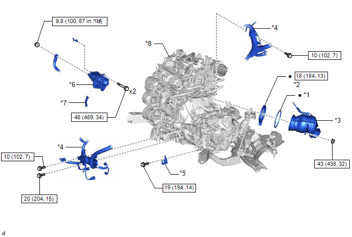
| *1 | TURBINE OUTLET ELBOW GASKET | *2 | EXHAUST PIPE CLAMP |
| *3 | EXHAUST MANIFOLD CONVERTER SUB-ASSEMBLY | *4 | ENGINE WIRE |
| *5 | NO. 2 CLUTCH FLEXIBLE HOSE BRACKET | *6 | STARTER ASSEMBLY |
| *7 | FLYWHEEL HOUSING SIDE COVER | *8 | ENGINE ASSEMBLY WITH TRANSAXLE |
 | Tightening torque for "Major areas involving basic vehicle performance such as moving/turning/stopping": N*m (kgf*cm, ft.*lbf) |
 | N*m (kgf*cm, ft.*lbf): Specified torque |
| ● | Non-reusable part | - | - |
ILLUSTRATION
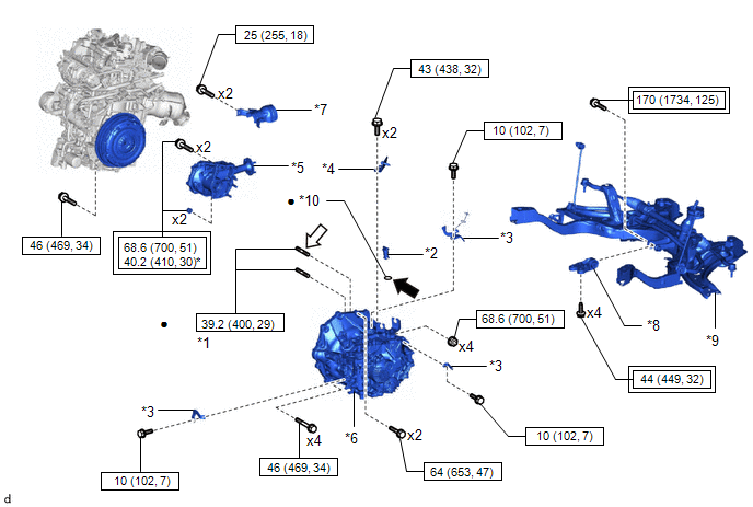
| *1 | TRANSFER AND TRANSAXLE SETTING STUD BOLT | *2 | MANUAL TRANSMISSION CASE PLUG |
| *3 | WIRE HARNESS CLAMP BRACKET | *4 | EXHAUST PIPE SUPPORT STAY |
| *5 | TRANSFER ASSEMBLY | *6 | MANUAL TRANSAXLE ASSEMBLY |
| *7 | PROPELLER SHAFT HEAT INSULATOR | *8 | NO. 2 ENGINE MOVING CONTROL ROD |
| *9 | FRONT SUSPENSION CROSSMEMBER SUB-ASSEMBLY | *10 | O-RING |
 | Tightening torque for "Major areas involving basic vehicle performance such as moving/turning/stopping": N*m (kgf*cm, ft.*lbf) |
 | N*m (kgf*cm, ft.*lbf): Specified torque |
| * | For use with SST and union nut wrench | ● | Non-reusable part |
 | Gear oil |
 | Adhesive 1324 |
| ★ | Precoated part | - | - |
ILLUSTRATION
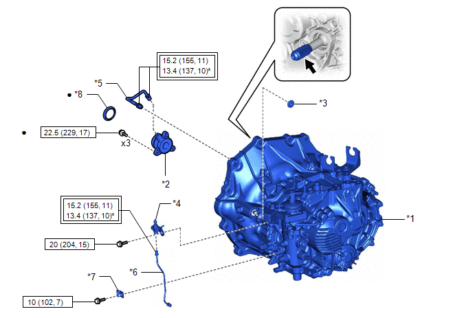
| *1 | MANUAL TRANSAXLE ASSEMBLY | *2 | CLUTCH RELEASE CYLINDER WITH BEARING ASSEMBLY |
| *3 | CLUTCH TUBE BOOT | *4 | CLUTCH RELEASE BLEEDER SUB-ASSEMBLY |
| *5 | CLUTCH RELEASE CYLINDER TO BLEEDER TUBE | *6 | BLEEDER CLUTCH RELEASE TUBE |
| *7 | CLAMP | *8 | CLUTCH RELEASE BEARING PLATE |
 | Tightening torque for "Major areas involving basic vehicle performance such as moving/turning/stopping": N*m (kgf*cm, ft.*lbf) |
 | N*m (kgf*cm, ft.*lbf): Specified torque |
| * | For use with union nut wrench | ● | Non-reusable part |
 | Clutch spline grease | ★ | Precoated part |

 Removal
REMOVAL CAUTION / NOTICE / HINT The necessary procedures (adjustment, calibration, initialization, or registration) that must be performed after parts are removed and installed, or replaced during the manual transaxle assembly removal/installation are shown below...
Other information:
Toyota Yaris XP210 (2020-2026) Reapir and Service Manual: Installation
INSTALLATION CAUTION / NOTICE / HINT CAUTION: Wear protective gloves. Sharp areas on the parts may injure your hands. There is risk of injury. HINT: Use the same procedure for the driver side and front passenger side. The procedure listed below is for the driver side...
Toyota Yaris XP210 (2020-2026) Reapir and Service Manual: On-vehicle Inspection
ON-VEHICLE INSPECTION PROCEDURE 1. CHECK AUXILIARY BATTERY CONDITION NOTICE: If the auxiliary battery is weak or if the engine is difficult to start, recharge the auxiliary battery and perform inspections again before returning the vehicle to the customer...
Categories
- Manuals Home
- Toyota Yaris Owners Manual
- Toyota Yaris Service Manual
- Immobilizer System
- Opening and Closing the Liftgate/Trunk Lid
- Headlights
- New on site
- Most important about car
Fuel Gauge
The fuel gauge shows approximately how much fuel is remaining in the tank when the ignition is switched ON. We recommend keeping the tank over 1/4 full.
