
Toyota Yaris: Power Window Regulator Motor / Components
COMPONENTS
ILLUSTRATION
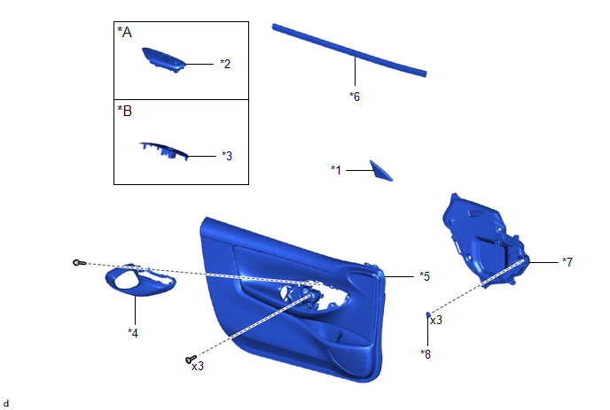
| *A | for Driver Side | *B | for Front Passenger Side |
| *1 | FRONT DOOR LOWER FRAME BRACKET GARNISH | *2 | MULTIPLEX NETWORK MASTER SWITCH ASSEMBLY WITH FRONT ARMREST BASE UPPER PANEL |
| *3 | POWER WINDOW REGULATOR SWITCH ASSEMBLY WITH FRONT ARMREST BASE UPPER PANEL | *4 | FRONT DOOR TRIM GARNISH |
| *5 | FRONT DOOR TRIM BOARD SUB-ASSEMBLY | *6 | FRONT DOOR GLASS INNER WEATHERSTRIP |
| *7 | FRONT DOOR SERVICE HOLE COVER | *8 | FRONT DOOR SERVICE HOLE COVER CLIP |
ILLUSTRATION
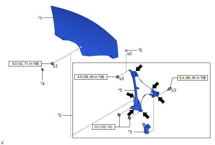
| *1 | FRONT DOOR GLASS SUB-ASSEMBLY | *2 | FRONT DOOR WINDOW REGULATOR ASSEMBLY |
| *3 | POWER WINDOW REGULATOR MOTOR ASSEMBLY | *4 | HOLE PLUG |
| *5 | FRONT DOOR WINDOW REGULATOR SUB- ASSEMBLY | *6 | WINDOW REGULATOR SHIM |
.png) | N*m (kgf*cm, ft.*lbf): Specified torque |
.png) | MP grease |

 Removal
REMOVAL CAUTION / NOTICE / HINT The necessary procedures (adjustment, calibration, initialization or registration) that must be performed after parts are removed and installed, or replaced during the power window regulator motor removal/installation are shown below...
Other information:
Toyota Yaris XP210 (2020-2026) Reapir and Service Manual: Left Rear Wheel Speed Sensor Signal Stuck Low (C050C23)
DESCRIPTION Refer to DTC C050C1F. Click here DTC No. Detection Item DTC Detection Condition Trouble Area DTC Output from C050C23 Left Rear Wheel Speed Sensor Signal Stuck Low Any of the following is detected: When the +BS terminal voltage is 17...
Toyota Yaris XP210 (2020-2026) Owner's Manual: Fuel Economy Data Reset and Trip Meter (TRIP A) Synchronization (Linking)
Because the average fuel economy indication on the instrument cluster display is linked with the “Average Fuel Economy History” (Current) indication on the center display, when one is reset the other is also reset. In addition, switching between reset and no reset of the average fuel economy indication on the instrument cluster display and the “Average Fuel Economy History” (Current) indication on the center display when resetting the trip meter (Trip A) is possible...
Categories
- Manuals Home
- Toyota Yaris Owners Manual
- Toyota Yaris Service Manual
- G16e-gts (engine Mechanical)
- Diagnostic Trouble Code Chart
- Immobilizer System
- New on site
- Most important about car
Supplemental Restraint System (SRS) Precautions
The front and side supplemental restraint systems (SRS) include different types of air bags. Please verify the different types of air bags which are equipped on your vehicle by locating the “SRS AIRBAG” location indicators. These indicators are visible in the area where the air bags are installed.
The air bags are installed in the following locations:
The steering wheel hub (driver air bag) The front passenger dashboard (front passenger air bag) The outboard sides of the front seatbacks (side air bags) The front and rear window pillars, and the roof edge along both sides (curtain air bags)