Toyota Yaris: Output Shaft / Inspection
INSPECTION
PROCEDURE
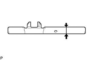
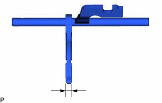
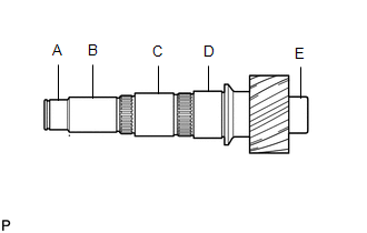
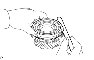
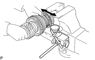
1. INSPECT NO. 1 OUTPUT SHAFT
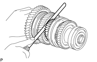
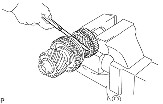
| (a) Check the No. 1 output shaft for wear and damage. |
|
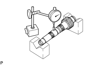
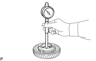
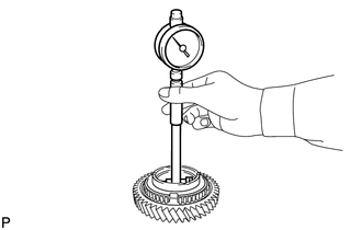
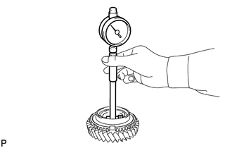
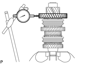
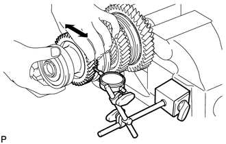
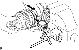
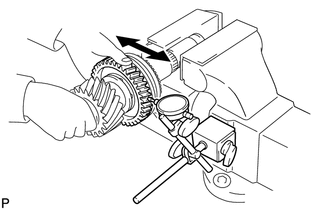
(b) Using a dial indicator, check the No. 1 output shaft runout.
Maximum Runout:
0.01 mm (0.000394 in.)
(1) If the runout exceeds the maximum, replace the No. 1 output shaft.
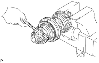
| (c) Using a micrometer, measure the outer diameter of the No. 1 output shaft journal surface. Standard:
(1) If the outer diameter is below the minimum, replace the No. 1 output shaft. |
|
2. INSPECT NO. 1 GEAR SHIFT FORK
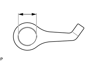
| (a) Using a micrometer, measure the outer diameter of the No. 1 gear shift fork. Standard Outer Diameter: 13.982 to 14.00 mm (0.5505 to 0.5512 in.) Minimum Outer Diameter: 13.982 mm (0.5505 in.) (1) If the outer diameter is less than the minimum, replace the No. 1 gear shift fork. |
|
3. INSPECT 3RD AND 4TH SHIFT FORK SHAFT
| (a) Using a micrometer, measure the outer diameter of the 3rd and 4th shift fork shaft. Standard Outer Diameter: 13.982 to 14.00 mm (0.5505 to 0.5512 in.) Minimum Outer Diameter: 13.982 mm (0.5505 in.) (1) If the outer diameter is less than the minimum, replace the 3rd and 4th shift fork shaft. |
|
4. INSPECT NO. 3 GEAR SHIFT FORK
| (a) Using a micrometer, measure the outer diameter of the 5th and 6th shift fork shaft. Standard Outer Diameter: 13.982 to 14.00 mm (0.5505 to 0.5512 in.) Minimum Outer Diameter: 13.982 mm (0.5505 in.) (1) If the outer diameter is less than the minimum, replace the 5th and 6th shift fork shaft. |
|
5. INSPECT REVERSE SHIFT FORK SHAFT
| (a) Using a micrometer, measure the outer diameter of the reverse shift fork shaft. Standard Outer Diameter: 13.982 to 14.00 mm (0.5505 to 0.5512 in.) Minimum Outer Diameter: 13.982 mm (0.5505 in.) (1) If the outer diameter is less than the minimum, replace the reverse shift fork shaft. |
|
6. INSPECT NO. 5 GEAR SHIFT FORK SHAFT
| (a) Using a micrometer, measure the outer diameter of the No. 5 gear shift fork shaft. Standard Outer Diameter: 15.966 to 15.984 mm (0.6286 to 0.6293 in.) Minimum Outer Diameter: 15.966 mm (0.6286 in.) (1) If the outer diameter is less than the minimum, replace the No. 5 gear shift fork shaft. |
|
7. INSPECT NO. 1 GEAR SHIFT FORK
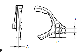
| (a) Using a vernier caliper, measure the No. 1 gear shift fork. Standard Thickness: 9.50 to 9.80 mm (0.374 to 0.386 in.) (1) If the inside diameter or thickness is not as specified, replace the No. 1 gear shift fork. |
|
8. INSPECT NO. 2 GEAR SHIFT FORK
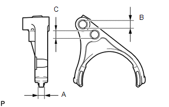
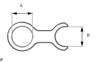
| (a) Using a vernier caliper, measure the No. 2 gear shift fork. Standard Inside Diameter and Thickness: A 9.50 to 9.80 mm (0.374 to 0.386 in.) B 14.010 to 14.043 mm (0.552 to 0.553 in.) C 14.70 to 15.30 mm (0.579 to 0.602 in.) (1) If the inside diameter or thickness is not as specified, replace the No. 2 gear shift fork. |
|
9. INSPECT NO. 3 GEAR SHIFT FORK
| (a) Using a vernier caliper, measure the No. 3 gear shift fork. Standard Thickness: 9.50 to 9.80 mm (0.374 to 0.386 in.) (1) If the inside diameter or thickness is not as specified, replace the No. 3 gear shift fork. |
|
10. INSPECT REVERSE SHIFT FORK
| (a) Using a vernier caliper, measure the reverse shift fork. Standard Inside Diameter and Thickness: A 4.40 to 4.56 mm (0.173 to 0.178 in.) B 14.010 to 14.043 mm (0.552 to 0.553 in.) C 14.7 to 15.3 mm (0.579 to 0.602 in.) (1) If the inside diameter or thickness is not as specified, replace the reverse shift fork. |
|
11. INSPECT NO. 2 GEAR SHIFT HEAD
| (a) Using a vernier caliper, measure the No. 2 gear shift head. Standard Inside Diameter: 13.994 to 14.054 mm (0.551 to 0.553 in.) Maximum Inside Diameter: 14.054 mm (0.553 in.) (1) If the inside diameter exceeds the maximum, replace the No. 2 gear shift head. |
|
12. INSPECT NO. 3 GEAR SHIFT HEAD
| (a) Using a vernier caliper, measure the No. 3 gear shift head. Standard Inside Diameter: A 15.994 to 16.054 mm (0.630 to 0.632 in.) B 14.20 to 14.25 mm (0.559 to 0.561 in.) Maximum Inside Diameter: A 16.054 mm (0.632 in.) B 14.25 mm (0.561 in.) (1) If the inside diameter exceeds the maximum, replace the No. 3 gear shift head. |
|
13. INSPECT 1ST DRIVEN GEAR
| (a) Using a cylinder gauge, measure the inside diameter of the 1st driven gear. Standard Inside Diameter: 53.015 to 53.040 mm (2.0872 to 2.0882 in.) Maximum Inside Diameter: 53.040 mm (2.0882 in.) (1) If the inside diameter exceeds the maximum, replace the 1st driven gear. |
|
14. INSPECT 2ND DRIVEN GEAR
| (a) Using a cylinder gauge, measure the inside diameter of the 2nd driven gear. Standard Inside Diameter: 56.015 to 56.030 mm (2.2053 to 2.2059 in.) Maximum Inside Diameter: 56.030 mm (2.2059 in.) (1) If the inside diameter exceeds the maximum, replace the 2nd driven gear. |
|
15. INSPECT 3RD DRIVEN GEAR
| (a) Using a cylinder gauge, measure the inside diameter of the 3rd driven gear. Standard Inside Diameter: 42.015 to 42.040 mm (1.6541 to 1.6551 in.) Maximum Inside Diameter: 42.040 mm (1.6551 in.) (1) If the inside diameter exceeds the maximum, replace the 3rd driven gear. |
|
16. INSPECT 4TH DRIVEN GEAR
| (a) Using a cylinder gauge, measure the inside diameter of the 4th driven gear. Standard Inside Diameter: 48.015 to 48.040 mm (1.8904 to 1.8913 in.) Maximum Inside Diameter: 48.040 mm (1.8913 in.) (1) If the inside diameter exceeds the maximum, replace the 4th driven gear. |
|
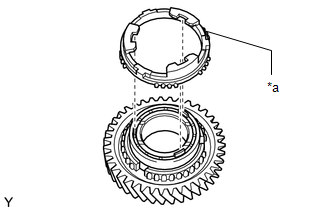
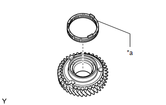
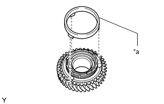
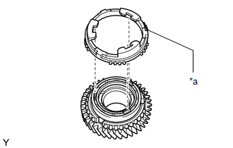
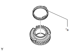
17. INSPECT 1ST DRIVEN GEAR SYNCHRONIZER RING SET
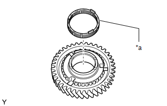
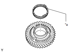
| *a | Inner Ring |
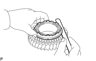
(a) Coat the 1st driven gear synchronizer ring set with gear oil.
(b) Install the inner ring to the 1st driven gear.
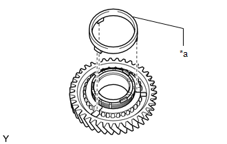
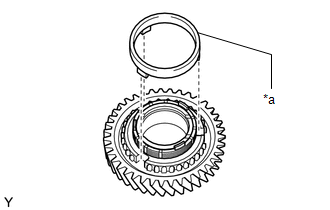
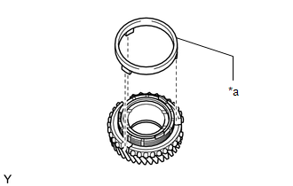
| (c) Install the middle ring to the 1st driven gear. |
|
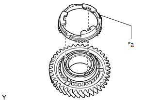
| (d) Install the outer ring to the 1st driven gear. |
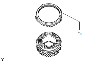
|
| (e) Coat the 1st driven gear with gear oil. |
|
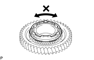
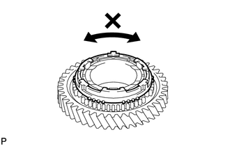
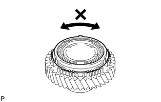
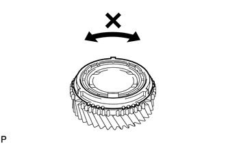
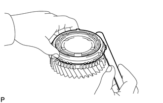
(f) Check that the 1st driven gear synchronizer ring set does not turn when the 1st driven gear synchronizer ring set is pushed to the 1st driven gear.
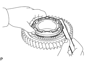
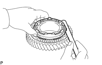
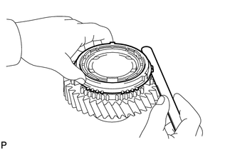
| (g) Using a feeler gauge, measure the clearance between the 1st driven gear synchronizer ring set back and the gear spline end. Standard Clearance: 0.98 to 1.82 mm (0.0386 to 0.0717 in.) Minimum Clearance: 0.98 mm (0.0386 in.) (1) If the clearance is below the minimum, replace the 1st driven gear synchronizer ring set. |
|
18. INSPECT 2ND DRIVEN GEAR SYNCHRONIZER RING SET
| *a | Inner Ring |
(a) Coat the 2nd driven gear synchronizer ring set with gear oil.
(b) Install the inner ring to the 2nd driven gear.
| (c) Install the middle ring to the 2nd driven gear. |
|
| (d) Install the outer ring to the 2nd driven gear. |
|
| (e) Coat the 2nd driven gear with gear oil. |
|
(f) Check that the 2nd driven gear synchronizer ring set does not turn when the 2nd driven gear synchronizer ring set is pushed to the 2nd driven gear.
| (g) Using a feeler gauge, measure the clearance between the 2nd driven gear synchronizer ring set back and the gear spline end. Standard Clearance: 1.28 to 2.12 mm (0.0504 to 0.0835 in.) Minimum Clearance: 2.12 mm (0.0835 in.) (1) If the clearance is below the minimum, replace the 2nd driven gear synchronizer ring set. |
|
19. INSPECT 3RD DRIVEN GEAR SYNCHRONIZER RING SET
| *a | Inner Ring |
(a) Coat the 3rd driven gear synchronizer ring set with gear oil.
(b) Install the inner ring to the 3rd driven gear.
| (c) Install the middle ring to the 3rd driven gear. |
|
| (d) Install the outer ring to the 3rd driven gear. |
|
| (e) Coat the 3rd driven gear with gear oil. |
|
(f) Check that the 3rd driven gear synchronizer ring set does not turn when the 3rd driven gear synchronizer ring set is pushed to the 3rd driven gear.
| (g) Using a feeler gauge, measure the clearance between the 3rd driven gear synchronizer ring set back and the gear spline end. Standard Clearance: 1.00 to 2.00 mm (0.0394 to 0.0787 in.) Minimum Clearance: 1.00 mm (0.0394 in.) (1) If the clearance is below the minimum, replace the 3rd driven gear synchronizer ring set. |
|
20. INSPECT 4TH DRIVEN GEAR SYNCHRONIZER RING SET
| *a | Inner Ring |
(a) Coat the 4th driven gear synchronizer ring set with gear oil.
(b) Install the inner ring to the 4th driven gear.
| (c) Install the middle ring to the 4th driven gear. |
|
| (d) Install the outer ring to the 4th driven gear. |
|
| (e) Coat the 4th driven gear with gear oil. |
|
(f) Check that the 4th driven gear synchronizer ring set does not turn when the 4th driven gear synchronizer ring set is pushed to the 4th driven gear.
| (g) Using a feeler gauge, measure the clearance between the 4th driven gear synchronizer ring set back and the gear spline end. Standard Clearance: 0.92 to 1.88 mm (0.0362 to 0.074 in.) Minimum Clearance: 0.92 mm (0.0362 in.) (1) If the clearance is below the minimum, replace the 4th driven gear synchronizer ring set. |
|
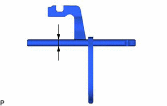
21. INSPECT NO. 1 TRANSMISSION HUB SLEEVE
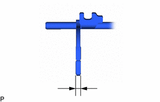
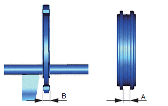
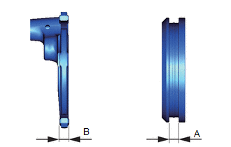
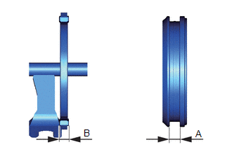
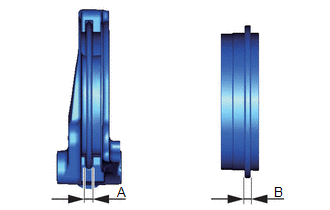
| (a) Using a vernier caliper, measure the clearance between the No. 1 transmission hub sleeve and the No. 1 gear shift fork. Standard Clearance (A - B): 0.10 to 0.50 mm (0.00394 to 0.0197 in.) (1) If the clearance is outside the specifications, replace the No. 1 transmission hub sleeve and No. 1 gear shift fork. |
|
22. INSPECT NO. 2 TRANSMISSION HUB SLEEVE
| (a) Using a vernier caliper, measure the clearance between the No. 2 transmission hub sleeve and the No. 2 gear shift fork. Standard Clearance (A - B): 0.35 to 0.75 mm (0.0138 to 0.0295 in.) (1) If the clearance is outside the specifications, replace the No. 2 transmission hub sleeve and No. 2 gear shift fork. |
|
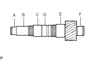
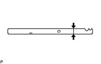
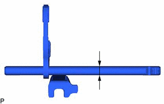
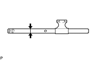
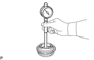
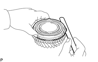
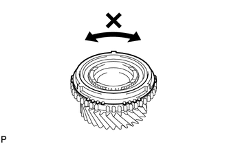
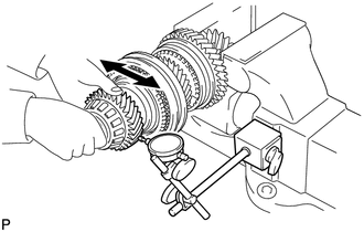
23. INSPECT NO. 2 OUTPUT SHAFT
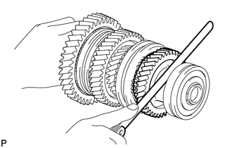
| (a) Check the No. 2 output shaft for wear and damage. |
|
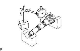
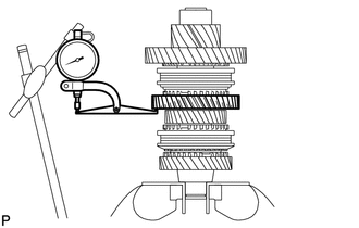
(b) Using a dial indicator, check the No. 2 output shaft runout.
Maximum Runout:
0.01 mm (0.000394 in.)
(1) If the runout exceeds the maximum, replace the No. 2 output shaft.
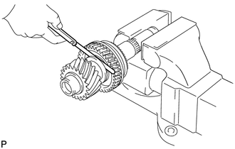
| (c) Using a micrometer, measure the outer diameter of the No. 2 output shaft journal surface. Standard:
(1) If the outer diameter is below the minimum, replace the No. 2 output shaft. |
|
24. INSPECT 5TH DRIVEN GEAR
| (a) Using a cylinder gauge, measure the inside diameter of the 5th driven gear. Standard Inside Diameter: 48.015 to 48.040 mm (1.8904 to 1.8913 in.) Maximum Inside Diameter: 48.040 mm (1.8913 in.) (1) If the inside diameter exceeds the maximum, replace the 5th driven gear. |
|

25. INSPECT 6TH DRIVEN GEAR
| (a) Using a cylinder gauge, measure the inside diameter of the 6th driven gear. Standard Inside Diameter: 42.015 to 42.040 mm (1.6541 to 1.6551 in.) Maximum Inside Diameter: 42.040 mm (1.6551 in.) (1) If the inside diameter exceeds the maximum, replace the 6th driven gear. |
|
26. INSPECT REVERSE DRIVEN GEAR
| (a) Using a cylinder gauge, measure the inside diameter of the reverse driven gear. Standard Inside Diameter: 53.015 to 53.040 mm (2.0872 to 2.0882 in.) Maximum Inside Diameter: 53.040 mm (2.0882 in.) (1) If the inside diameter exceeds the maximum, replace the reverse driven gear. |
|
27. INSPECT 5TH DRIVEN GEAR SYNCHRONIZER RING
| (a) Coat the 5th driven gear with gear oil. |
|
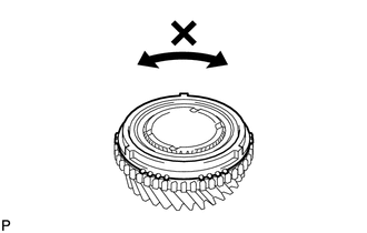
(b) Check that the 5th driven gear synchronizer ring does not turn when the 5th driven gear synchronizer ring is pushed to the 5th driven gear.
| (c) Using a feeler gauge, measure the clearance between the 5th driven gear synchronizer ring back and the gear spline end. Standard Clearance: 0.80 to 1.60 mm (0.0315 to 0.063 in.) Minimum Clearance: 0.80 mm (0.0315 in.) (1) If the clearance is below the minimum, replace the 5th driven gear synchronizer ring. |
|
28. INSPECT 6TH DRIVEN GEAR SYNCHRONIZER RING
| (a) Coat the 6th driven gear with gear oil. |
|
(b) Check that the 6th driven gear synchronizer ring does not turn when the 6th driven gear synchronizer ring is pushed to the 6th driven gear.
| (c) Using a feeler gauge, measure the clearance between the 6th driven gear synchronizer ring back and the gear spline end. Standard Clearance: 0.80 to 1.60 mm (0.0315 to 0.063 in.) Minimum Clearance: 0.80 mm (0.0315 in.) (1) If the clearance is below the minimum, replace the 6th driven gear synchronizer ring. |
|
29. INSPECT REVERSE DRIVEN GEAR SYNCHRONIZER RING
| (a) Coat the reverse driven gear with gear oil. |
|
(b) Check that the reverse driven gear synchronizer ring does not turn when the reverse driven gear synchronizer ring is pushed to the reverse driven gear.
| (c) Using a feeler gauge, measure the clearance between the reverse driven gear synchronizer ring back and the gear spline end. Standard Clearance: 0.68 to 1.32 mm (0.0268 to 0.052 in.) Minimum Clearance: 0.68 mm (0.0268 in.) (1) If the clearance is below the minimum, replace the reverse driven gear synchronizer ring. |
|
30. INSPECT NO. 3 TRANSMISSION HUB SLEEVE
| (a) Using a vernier caliper, measure the clearance between the No. 3 transmission hub sleeve and the No. 3 gear shift fork. Standard Clearance (A - B): 0.10 to 0.50 mm (0.00394 to 0.0197 in.) (1) If the clearance is outside the specifications, replace the No. 3 transmission hub sleeve and No. 3 gear shift fork. |
|
31. INSPECT NO. 4 TRANSMISSION HUB SLEEVE
| (a) Using a vernier caliper, measure the clearance between the No. 4 transmission hub sleeve and the reverse shift fork. Standard Clearance (A - B): 0.15 to 0.41 mm (0.00591 to 0.0161 in.) (1) If the clearance is outside the specifications, replace the No. 4 transmission hub sleeve and reverse shift fork. |
|
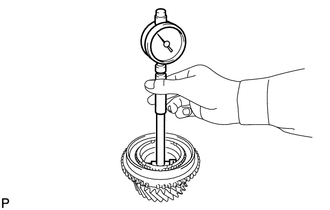
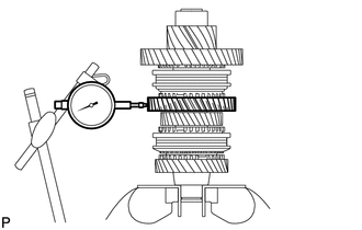
32. INSPECT 1ST DRIVEN GEAR THRUST CLEARANCE
| (a) Using a dial indicator, measure the 1st driven gear thrust clearance. Standard Clearance: 0.10 to 0.35 mm (0.00394 to 0.0138 in.) Maximum Clearance: 0.35 mm (0.0138 in.) (1) If the clearance exceeds the maximum, replace the 1st driven gear, needle roller bearing or No. 1 output shaft. |
|
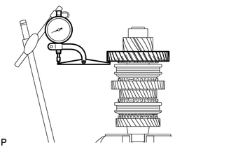
33. INSPECT 1ST DRIVEN GEAR RADIAL CLEARANCE
| (a) Using a dial indicator, measure the 1st driven gear radial clearance. Standard Clearance: 0.015 to 0.068 mm (0.000591 to 0.00268 in.) Maximum Clearance: 0.068 mm (0.00268 in.) (1) If the clearance exceeds the maximum, replace the 1st driven gear, needle roller bearing or No. 1 output shaft. |
|
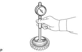
34. INSPECT 2ND DRIVEN GEAR THRUST CLEARANCE
| (a) Using a dial indicator, measure the 2nd driven gear thrust clearance. Standard Clearance: 0.11 to 0.46 mm (0.00433 to 0.0181 in.) Maximum Clearance: 0.46 mm (0.0181 in.) (1) If the clearance exceeds the maximum, replace the 2nd driven gear, needle roller bearing or No. 1 output shaft. |
|
35. INSPECT 2ND DRIVEN GEAR RADIAL CLEARANCE
| (a) Using a dial indicator, measure the 2nd driven gear radial clearance. Standard Clearance: 0.015 to 0.048 mm (0.000591 to 0.00189 in.) Maximum Clearance: 0.048 mm (0.00189 in.) (1) If the clearance exceeds the maximum, replace the 2nd driven gear, needle roller bearing or No. 1 output shaft. |
|
36. INSPECT 3RD DRIVEN GEAR THRUST CLEARANCE
| (a) Using a feeler gauge, measure the 3rd driven gear thrust clearance. Standard Clearance: 0.11 to 0.54 mm (0.00433 to 0.0213 in.) Maximum Clearance: 0.54 mm (0.0213 in.) (1) If the clearance exceeds the maximum, replace the 3rd driven gear, needle roller bearing or No. 1 output shaft. |
|
37. INSPECT 3RD DRIVEN GEAR RADIAL CLEARANCE
| (a) Using a dial indicator, measure the 3rd driven gear radial clearance. Standard Clearance: 0.015 to 0.066 mm (0.000591 to 0.0026 in.) Maximum Clearance: 0.066 mm (0.0026 in.) (1) If the clearance exceeds the maximum, replace the 3rd driven gear, needle roller bearing or No. 1 output shaft. |
|
38. INSPECT 4TH DRIVEN GEAR THRUST CLEARANCE
| (a) Using a feeler gauge, measure the 4th driven gear thrust clearance. Standard Clearance: 0.10 to 0.65 mm (0.00394 to 0.0256 in.) Maximum Clearance: 0.65 mm (0.0256 in.) (1) If the clearance exceeds the maximum, replace the 4th driven gear, needle roller bearing or No. 1 output shaft. |
|
39. INSPECT 4TH DRIVEN GEAR RADIAL CLEARANCE
| (a) Using a dial indicator, measure the 4th driven gear radial clearance. Standard Clearance: 0.015 to 0.066 mm (0.000591 to 0.0026 in.) Maximum Clearance: 0.066 mm (0.0026 in.) (1) If the clearance exceeds the maximum, replace the 4th driven gear, needle roller bearing or No. 1 output shaft. |
|
40. INSPECT 5TH DRIVEN GEAR THRUST CLEARANCE
| (a) Using a feeler gauge, measure the 5th driven gear thrust clearance. Standard Clearance: 0.10 to 0.55 mm (0.00394 to 0.0217 in.) Maximum Clearance: 0.55 mm (0.0217 in.) (1) If the clearance exceeds the maximum, replace the 5th driven gear, needle roller bearing or No. 2 output shaft. |
|
41. INSPECT 5TH DRIVEN GEAR RADIAL CLEARANCE
| (a) Using a dial indicator, measure the 5th driven gear radial clearance. Standard Clearance: 0.015 to 0.066 mm (0.000591 to 0.0026 in.) Maximum Clearance: 0.066 mm (0.0026 in.) (1) If the clearance exceeds the maximum, replace the 5th driven gear, needle roller bearing or No. 2 output shaft. |
|
42. INSPECT 6TH DRIVEN GEAR THRUST CLEARANCE
| (a) Using a feeler gauge, measure the 6th driven gear thrust clearance. Standard Clearance: 0.10 to 0.55 mm (0.00394 to 0.0217 in.) Maximum Clearance: 0.55 mm (0.0217 in.) (1) If the clearance exceeds the maximum, replace the 6th driven gear, needle roller bearing or No. 2 output shaft. |
|
43. INSPECT 6TH DRIVEN GEAR RADIAL CLEARANCE
| (a) Using a dial indicator, measure the 6th driven gear radial clearance. Standard Clearance: 0.015 to 0.066 mm (0.000591 to 0.0026 in.) Maximum Clearance: 0.066 mm (0.0026 in.) (1) If the clearance exceeds the maximum, replace the 6th driven gear, needle roller bearing or No. 2 output shaft. |
|
44. INSPECT REVERSE DRIVEN GEAR THRUST CLEARANCE
| (a) Using a feeler gauge, measure the reverse driven gear thrust clearance. Standard Clearance: 0.11 to 0.34 mm (0.00433 to 0.0134 in.) Maximum Clearance: 0.34 mm (0.0134 in.) (1) If the clearance exceeds the maximum, replace the reverse driven gear, needle roller bearing or No. 2 output shaft. |
|
45. INSPECT REVERSE DRIVEN GEAR RADIAL CLEARANCE
| (a) Using a dial indicator, measure the reverse driven gear radial clearance. Standard Clearance: 0.015 to 0.068 mm (0.000591 to 0.00268 in.) Maximum Clearance: 0.068 mm (0.00268 in.) (1) If the clearance exceeds the maximum, replace the reverse driven gear, needle roller bearing or No. 2 output shaft. |
|
 Disassembly
DISASSEMBLY PROCEDURE 1. INSPECT 1ST DRIVEN GEAR THRUST CLEARANCE Click here
2. INSPECT 1ST DRIVEN GEAR RADIAL CLEARANCE Click here
3. INSPECT 2ND DRIVEN GEAR THRUST CLEARANCE Click here
4...
 Reassembly
REASSEMBLY PROCEDURE 1. INSTALL NEEDLE ROLLER BEARING (a) Coat the needle roller bearing with gear oil and install it to the No. 2 output shaft.
2...
Other information:
Toyota Yaris XP210 (2020-2026) Reapir and Service Manual: Freeze Frame Data
FREEZE FRAME DATA CHECK FREEZE FRAME DATA HINT: Whenever an active noise control system DTC is stored, the stereo component equalizer assembly stores the current vehicle state as freeze frame data. (a) Enter the following menus: Body Electrical / Active Noise Control / Trouble Codes...
Toyota Yaris XP210 (2020-2026) Owner's Manual: Keys
Smart key Auxiliary key Key code number plate To use the auxiliary key, press the knob and pull out the auxiliary key from the smart key. A code number is stamped on the plate attached to the key set; detach this plate and store it in a safe place (not in the vehicle) for use if you need to make a replacement key (auxiliary key)...
Categories
- Manuals Home
- Toyota Yaris Owners Manual
- Toyota Yaris Service Manual
- Diagnostic Trouble Code Chart
- Maintenance
- Opening and Closing the Liftgate/Trunk Lid
- New on site
- Most important about car
Liftgate/Trunk Lid
WARNING
Never allow a person to ride in the luggage compartment/trunk
Allowing a person to ride in the luggage compartment/trunk is dangerous. The person in the luggage compartment/trunk could be seriously injured or killed during sudden braking or a collision.
Do not drive with the liftgate/trunk lid open