Toyota Yaris: Output Shaft / Reassembly
REASSEMBLY
PROCEDURE
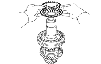
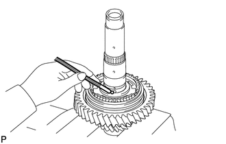
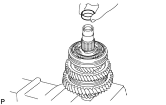
1. INSTALL NEEDLE ROLLER BEARING
| (a) Coat the needle roller bearing with gear oil and install it to the No. 2 output shaft. |
|
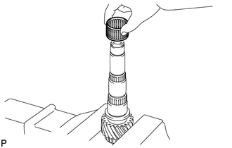
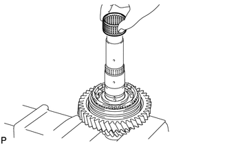
2. INSTALL REVERSE DRIVEN GEAR
| (a) Coat the reverse driven gear with gear oil and install it to the No. 2 output shaft. |
|
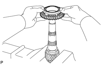
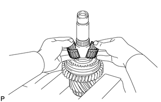
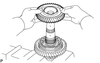
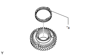
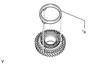
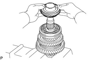
3. INSTALL NO. 4 TRANSMISSION CLUTCH HUB
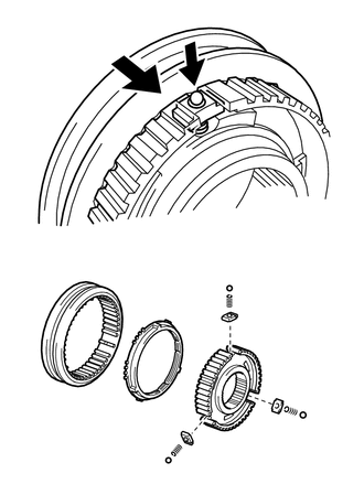
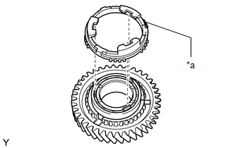
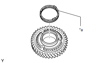
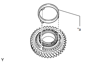
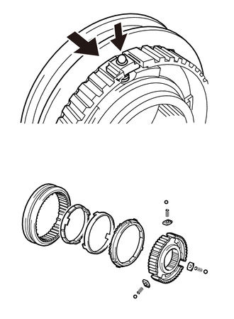
| (a) Install the reverse driven gear synchronizer ring, key spring and shifting key to the No. 4 transmission clutch hub. HINT:
|
|

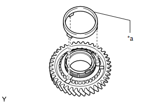
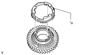
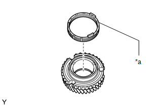
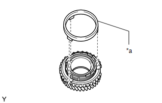
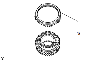
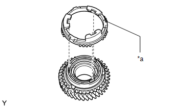
(b) Install the No. 4 transmission hub sleeve to the reverse driven gear as shown in the illustration.
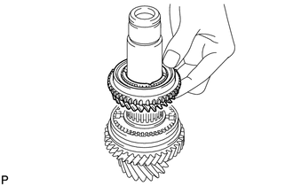
| (c) Coat the No. 4 transmission clutch hub with gear oil and install it to the No. 2 output shaft. |
|
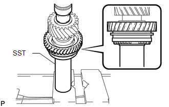
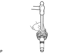
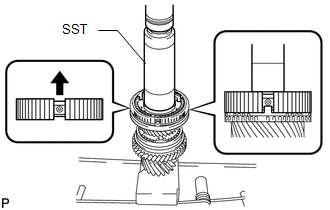
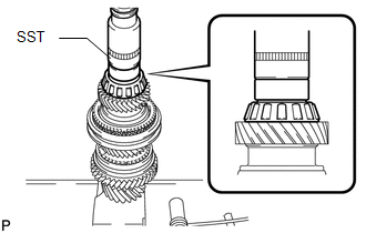
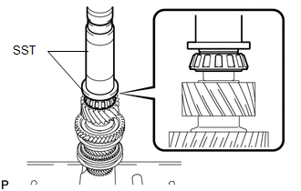
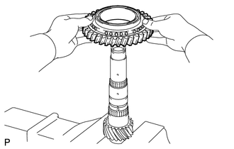
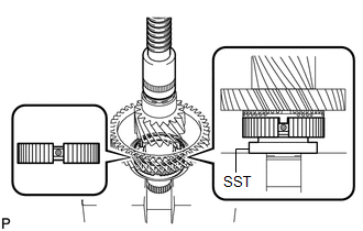
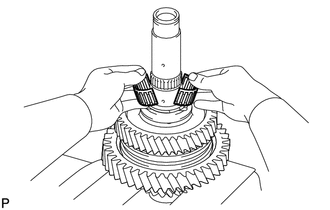
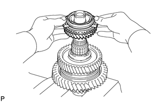
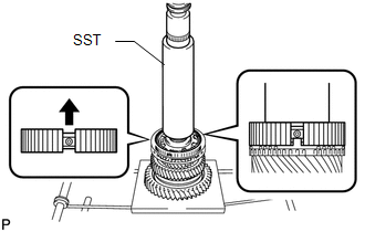
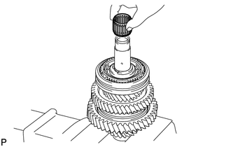
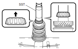
(d) Using SST and a press, install the reverse driven gear and No. 4 transmission clutch hub to the No. 2 output shaft.
SST: 09308-14010
NOTICE:
After installation, make sure that the gear and synchronizer ring move smoothly.
HINT:
Make sure that the protruding part on the reverse driven gear synchronizer ring is fitted into the groove of the No. 4 transmission clutch hub.
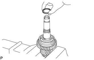
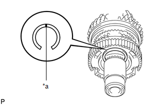
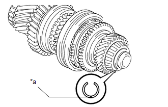
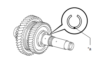
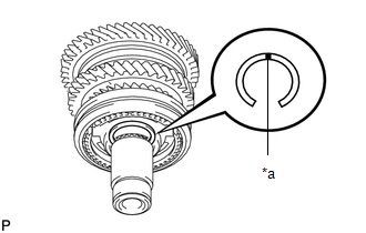
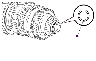
4. INSTALL SHAFT SNAP RING
| (a) Select a new shaft snap ring, using the table below, that makes the thrust clearance of the No. 4 transmission clutch hub less than 0.1 mm (0.00394 in.). Shaft Snap Ring Thickness:
|
|
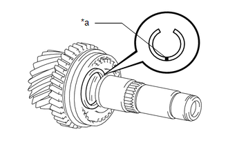
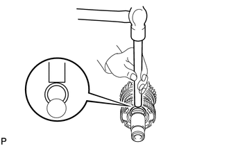
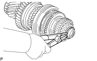
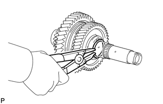
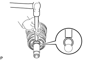
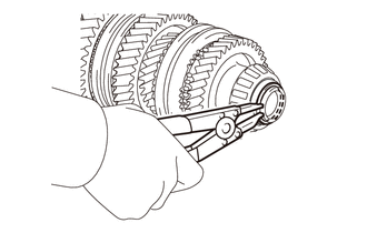
| (b) Using a brass bar and hammer, tap the shaft snap ring to the No. 2 output shaft. |
|
5. INSPECT REVERSE DRIVEN GEAR THRUST CLEARANCE
Click here

6. INSPECT REVERSE DRIVEN GEAR RADIAL CLEARANCE
Click here

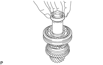
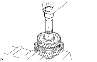
7. INSTALL 5TH DRIVEN GEAR
| (a) Install the spacer to the No. 2 output shaft. |
|
| (b) Coat the needle roller bearing with gear oil and install it to the No. 2 output shaft. |
|
| (c) Install the spacer to the No. 2 output shaft. |
|
| (d) Coat the 5th driven gear with gear oil and install it to the No. 2 output shaft. |
|
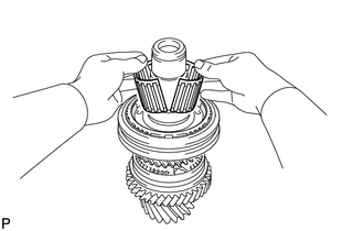
8. INSTALL NO. 3 TRANSMISSION CLUTCH HUB
| (a) Apply gear oil to the No. 3 transmission hub sleeve and No. 3 transmission clutch hub. |
|
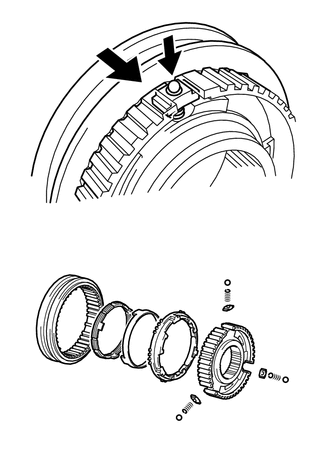
(b) Install the No. 3 transmission hub sleeve to the No. 3 transmission clutch hub.
(c) Install the 3 No. 1 synchromesh shifting keys to the No. 3 transmission clutch hub.
(d) Install the 3 synchronizer shifting key springs to the No. 3 transmission clutch hub.
(e) Place the balls in the holes of the No. 1 synchromesh shifting keys and install the No. 3 transmission hub sleeve while pushing in the balls.
NOTICE:
Take care to prevent the balls from scattering.
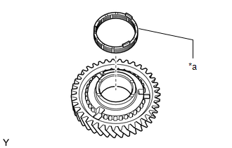
(f) Coat the 5th driven gear synchronizer ring with gear oil and install it to the 5th driven gear.
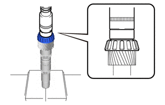
| (g) Using SST and a press, install the No. 3 transmission clutch hub to the No. 2 output shaft. SST: 09308-14010 NOTICE: After installation, make sure that the gear and synchronizer ring move smoothly. HINT: Make sure that the protruding part on the 5th driven gear synchronizer ring is fitted into the groove of the No. 3 transmission clutch hub. |
|
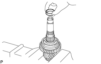
9. INSTALL SHAFT SNAP RING
| (a) Select a new shaft snap ring, using the table below, that makes the thrust clearance of the No. 3 transmission clutch hub less than 0.1 mm (0.00394 in.). Shaft Snap Ring Thickness:
|
|
| (b) Using a brass bar and hammer, tap the shaft snap ring to the No. 2 output shaft. |
|
10. INSPECT 5TH DRIVEN GEAR THRUST CLEARANCE
Click here

11. INSPECT 5TH DRIVEN GEAR RADIAL CLEARANCE
Click here

12. INSTALL 6TH DRIVEN GEAR
| (a) Install the spacer to the No. 2 output shaft. |
|
| (b) Coat the needle roller bearing with gear oil and install it to the No. 2 output shaft. |
|
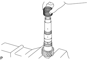
| (c) Coat the 6th driven gear synchronizer ring with gear oil and install it to the No. 3 transmission clutch hub. |
|
| (d) Coat the 6th driven gear with gear oil and install it to the No. 2 output shaft. |
|
13. INSTALL NO. 2 OUTPUT SHAFT REAR BEARING
| (a) Using SST and a press, install the No. 2 output shaft rear bearing to the No. 2 output shaft. SST: 09710-04071 NOTICE: After installation, make sure that the gear and synchronizer ring move smoothly. |
|
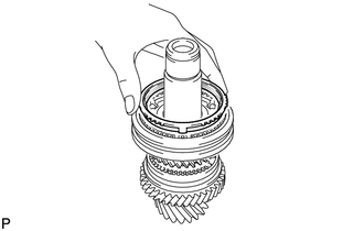
14. INSTALL NO. 2 OUTPUT SHAFT BEARING SNAP RING
| (a) Select a new No. 2 output shaft bearing snap ring, using the table below, that makes the thrust clearance of the No. 2 output shaft rear bearing less than 0.1 mm (0.00394 in.). No. 2 Output Shaft Bearing Snap Ring Thickness:
|
|
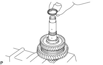
| (b) Using a snap ring expander, install the No. 2 output shaft bearing snap ring to the No. 2 output shaft. |
|
15. INSPECT 6TH DRIVEN GEAR THRUST CLEARANCE
Click here

16. INSPECT 6TH DRIVEN GEAR RADIAL CLEARANCE
Click here

17. INSTALL NO. 2 OUTPUT SHAFT FRONT BEARING
| (a) Using SST and a press, install the No. 2 output shaft front bearing to the No. 2 output shaft. SST: 09309-37010 SST: 09506-30012 |
|
18. INSTALL OUTPUT SHAFT FRONT BEARING INNER RACE
| (a) Using SST and a press, install the output shaft front bearing inner race to the No. 1 output shaft. SST: 09710-30012 09710-04091 |
|
19. INSTALL 1ST DRIVEN GEAR
| (a) Coat the needle roller bearing with gear oil and install it to the No. 1 output shaft. |
|
| (b) Install the inner ring to the 1st driven gear. |
|
| (c) Install the middle ring to the 1st driven gear. |
|
| (d) Install the outer ring to the 1st driven gear. |
|
| (e) Coat the 1st driven gear with gear oil and install it to the No. 1 output shaft. |
|
20. INSTALL NO. 1 TRANSMISSION CLUTCH HUB
| (a) Apply gear oil to the No. 1 transmission hub sleeve and No. 1 transmission clutch hub. |
|
(b) Install the No. 1 transmission hub sleeve to the No. 1 transmission clutch hub.
(c) Install the 3 No. 1 synchromesh shifting keys to the No. 1 transmission clutch hub.
(d) Install the 3 synchronizer shifting key springs to the No. 1 transmission clutch hub.
(e) Place the balls in the holes of the No. 1 synchromesh shifting keys and install the No. 1 transmission hub sleeve while pushing in the balls.
NOTICE:
Take care to prevent the balls from scattering.
(f) Coat the 1st driven gear synchronizer ring set with gear oil.
| (g) Using SST and a press, install the No. 1 transmission hub sleeve to the No. 1 output shaft. SST: 09726-40010 NOTICE: After installation, make sure that the gear and synchronizer ring move smoothly. HINT: Make sure that the protruding part on the 1st driven gear synchronizer ring set is fitted into the groove of the No. 1 transmission clutch hub. |
|
21. INSTALL 2ND DRIVEN GEAR SYNCHRONIZER RING SET
| (a) Coat the 2nd driven gear synchronizer ring set with gear oil. |
|
(b) Install the inner ring to the 2nd driven gear.
| (c) Install the middle ring to the 2nd driven gear. |
|
| (d) Install the outer ring to the 2nd driven gear. |
|
22. INSTALL SYNCHROMESH SHIFTING KEY BALL
| (a) Install the synchromesh shifting key ball to the No. 1 output shaft. |
|
23. INSTALL NEEDLE ROLLER BEARING
| (a) Coat the needle roller bearing with gear oil and install it to the No. 1 output shaft. |
|
24. INSTALL 2ND DRIVEN GEAR
| (a) Coat the 2nd driven gear with gear oil and install it to the No. 1 output shaft. |
|
25. INSTALL 2ND DRIVEN GEAR BEARING INNER RACE
| (a) Align the groove of the 2nd driven gear bearing inner race with the ball and install the inner race. |
|
26. INSTALL OUTPUT SHAFT BEARING SHAFT SNAP RING
| (a) Select a new output shaft bearing shaft snap ring, using the table below, that makes the thrust clearance of the 2nd driven gear bearing inner race less than 0.1 mm (0.00394 in.). Output Shaft Bearing Shaft Snap Ring Thickness:
|
|
| (b) Using a snap ring expander, install the output shaft bearing shaft snap ring to the No. 1 output shaft. HINT: Do not damage the journal surface of the No. 1 output shaft. |
|
27. INSPECT 1ST DRIVEN GEAR THRUST CLEARANCE
Click here

28. INSPECT 1ST DRIVEN GEAR RADIAL CLEARANCE
Click here

29. INSPECT 2ND DRIVEN GEAR THRUST CLEARANCE
Click here

30. INSPECT 2ND DRIVEN GEAR RADIAL CLEARANCE
Click here

31. INSTALL 4TH DRIVEN GEAR
| (a) Install the spacer to the No. 1 output shaft. |
|
| (b) Coat the needle roller bearing with gear oil and install it to the No. 1 output shaft. |
|
| (c) Install the inner ring to the 4th driven gear. |
|
| (d) Install the middle ring to the 4th driven gear. |
|
| (e) Install the outer ring to the 4th driven gear. |
|
| (f) Coat the 4th driven gear with gear oil and install it to the No. 1 output shaft. |
|
32. INSTALL NO. 2 TRANSMISSION CLUTCH HUB
| (a) Apply gear oil to the No. 2 transmission hub sleeve and No. 2 transmission clutch hub. |
|
(b) Install the No. 2 transmission hub sleeve to the No. 2 transmission clutch hub.
(c) Install the 3 No. 1 synchromesh shifting keys to the No. 2 transmission clutch hub.
(d) Install the 3 synchronizer shifting key springs to the No. 2 transmission clutch hub.
(e) Place the balls in the holes of the No. 1 synchromesh shifting keys and install the No. 2 transmission hub sleeve while pushing in the balls.
NOTICE:
Take care to prevent the balls from scattering.
(f) Coat the 4th driven gear synchronizer ring set with gear oil.
| (g) Using SST and a press, install the transmission clutch hub to the 4th driven gear. SST: 09309-14010 NOTICE: After installation, make sure that the gear and synchronizer ring move smoothly. HINT: Make sure that the protruding part on the 4th driven gear synchronizer ring set is fitted into the groove of the No. 2 transmission clutch hub. |
|
33. INSTALL SHAFT SNAP RING
| (a) Select a new shaft snap ring, using the table below, that makes the thrust clearance of the No. 2 transmission clutch hub less than 0.1 mm (0.00394 in.). Shaft Snap Ring Thickness:
|
|
| (b) Using a brass bar and hammer, tap the shaft snap ring to the No. 1 output shaft. |
|
34. INSPECT 4TH DRIVEN GEAR THRUST CLEARANCE
Click here

35. INSPECT 4TH DRIVEN GEAR RADIAL CLEARANCE
Click here

36. INSTALL 3RD DRIVEN GEAR
| (a) Coat the 3rd driven gear synchronizer ring set with gear oil. |
|
(b) Install the inner ring to the 3rd driven gear.
| (c) Install the middle ring to the 3rd driven gear. |
|
| (d) Install the outer ring to the 3rd driven gear. |
|
| (e) Coat the needle roller bearing with gear oil and install it to the No. 1 output shaft. |
|
| (f) Install the spacer to the No. 1 output shaft. |
|
| (g) Coat the 3rd driven gear with gear oil and install it to the No. 1 output shaft. |
|
37. INSTALL OUTPUT SHAFT REAR BEARING
| (a) Using SST and a press, install the output shaft rear bearing to the No. 1 output shaft. SST: 09308-14010 NOTICE: After installation, make sure that the gear and synchronizer ring move smoothly. HINT: When pressing in the bearing, apply force only to the inner race. Do not apply force to the seal. |
|
38. INSTALL OUTPUT SHAFT BEARING SHAFT SNAP RING
| (a) Select a new output shaft bearing shaft snap ring, using the table below, that makes the thrust clearance of the output shaft rear bearing less than 0.1 mm (0.00394 in.). Output Shaft Bearing Shaft Snap Ring Thickness:
|
|
| (b) Using a snap ring expander, install the output shaft bearing shaft snap ring to the No. 1 output shaft. |
|
39. INSPECT 3RD DRIVEN GEAR THRUST CLEARANCE
Click here

40. INSPECT 3RD DRIVEN GEAR RADIAL CLEARANCE
Click here

 Inspection
INSPECTION PROCEDURE 1. INSPECT NO. 1 OUTPUT SHAFT (a) Check the No. 1 output shaft for wear and damage.
(b) Using a dial indicator, check the No...

Other information:
Toyota Yaris XP210 (2020-2026) Reapir and Service Manual: Left Front Wheel Speed Sensor Signal Has Too Many Pulses (C05003A,C05063A)
DESCRIPTION Refer to DTC C05001F. Click here DTC No. Detection Item DTC Detection Condition Trouble Area DTC Output from C05003A Left Front Wheel Speed Sensor Signal Has Too Many Pulses When not in Dealer Mode (Signal Check) or Inspection Mode, the output of the speed sensor detected by the skid control ECU (brake actuator assembly) is too high for 5 second or more...
Toyota Yaris XP210 (2020-2026) Reapir and Service Manual: Removal
REMOVAL CAUTION / NOTICE / HINT The necessary procedures (adjustment, calibration, initialization, or registration) that must be performed after parts are removed and installed, or replaced during the rear drive shaft assembly removal/installation are shown below...
Categories
- Manuals Home
- Toyota Yaris Owners Manual
- Toyota Yaris Service Manual
- G16e-gts (engine Mechanical)
- Diagnostic Trouble Code Chart
- Opening and Closing the Liftgate/Trunk Lid
- New on site
- Most important about car
Refueling
Before refueling, close all the doors, windows, and the liftgate/trunk lid, and switch the ignition OFF.
To open the fuel-filler lid, pull the remote fuel-filler lid release.
