Toyota Yaris: Smart Key System (for Entry Function) / Front Passenger Side Electrical Antenna Circuit Open (B27A213)
DESCRIPTION
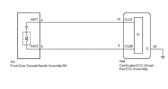
The certification ECU (smart key ECU assembly) generates a request signal and transmits the signal to the front door outside handle assembly RH (electrical key antenna) at intervals of 0.25 seconds. For the front door outside handle assembly RH (electrical key antenna) to detect when the electrical key transmitter sub-assembly is brought close to the vehicle, a signal requesting a response from the electrical key transmitter sub-assembly is transmitted within approximately 1 m (3.28 ft.) of the front passenger door at intervals of 0.25 seconds. DTC B27A213 is stored by the certification ECU (smart key ECU assembly) when an open is detected between the certification ECU (smart key ECU assembly) and front door outside handle assembly RH (electrical key antenna) (between terminals CLG2 and ANT1, or terminals CG2B and ANT2).
| DTC No. | Detection Item | INF Code | DTC Detection Condition | Note |
|---|---|---|---|---|
| B27A213 | Front Passenger Side Electrical Antenna Circuit Open | An open is detected in the circuit between the certification ECU (smart key ECU assembly) and front door outside handle assembly RH (CLG2 - ANT1, CG2B - ANT2) (This is detected by the malfunction detection circuit in the certification ECU (smart key ECU assembly)) (1 trip detection logic*). |
|
|
- *: Only output while a malfunction is present.
| Vehicle Condition when Malfunction Detected | Fail-safe Operation when Malfunction Detected |
|---|---|
| Entry lock/unlock operation cannot be performed for front passenger door | - |
| DTC No. | Data List and Active Test |
|---|---|
| B27A213 | Key diagnostic mode can be used to perform troubleshooting |
WIRING DIAGRAM
CAUTION / NOTICE / HINT
NOTICE:
- When using the GTS with the ignition switch off, connect the GTS to the DLC3 and turn a courtesy light switch on and off at intervals of 1.5 seconds or less until communication between the GTS and the vehicle begins. Then select the vehicle type under manual mode and enter the following menus: Body Electrical / Smart Key. While using the GTS, periodically turn a courtesy light switch on and off at intervals of 1.5 seconds or less to maintain communication between the GTS and the vehicle.
-
The smart key system (for Entry Function) uses the CAN communication system. Inspect the communication function by following How to Proceed with Troubleshooting. Troubleshoot the smart key system (for Entry Function) after confirming that the communication systems are functioning properly.
Click here

-
Before replacing the certification ECU (smart key ECU assembly), refer to Precaution.
Click here

- After repair, confirm that no DTCs are output by performing "DTC Output Confirmation Operation".
PROCEDURE
| 1. | CHECK CONNECTOR CONNECTION |
(a) Check that the connectors are properly connected to the certification ECU (smart key ECU assembly) and front door outside handle assembly RH.
OK:
Connectors are properly connected.
| NG |
 | CONNECT CONNECTORS PROPERLY |
|

| 2. | CHECK HARNESS AND CONNECTOR (CERTIFICATION ECU (SMART KEY ECU ASSEMBLY) - FRONT DOOR OUTSIDE HANDLE ASSEMBLY RH) |
(a) Disconnect the H46 certification ECU (smart key ECU assembly) connector.
(b) Disconnect the K4 front door outside handle assembly RH connector.
(c) Measure the resistance according to the value(s) in the table below.
Standard Resistance:
| Tester Connection | Condition | Specified Condition |
|---|---|---|
| H46-10 (CLG2) - K4-4 (ANT1) | Always | Below 1 Ω |
| H46-9 (CG2B) - K4-6 (ANT2) | Always | Below 1 Ω |
(d) Reconnect the H46 certification ECU (smart key ECU assembly) connector.
| NG |
 | REPAIR OR REPLACE HARNESS OR CONNECTOR |
|

| 3. | CHECK CERTIFICATION ECU (SMART KEY ECU ASSEMBLY) (OUTPUT TO FRONT DOOR OUTSIDE HANDLE ASSEMBLY RH) |
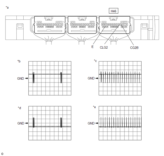
| *a | Component with harness connected (Certification ECU (Smart Key ECU Assembly)) | *b | Waveform 1 |
| *c | Waveform 2 | *d | Waveform 3 |
| *e | Waveform 4 | - | - |
(a) Using an oscilloscope, check the waveform.
OK:
| Tester Connection | Condition | Tool Setting | Specified Condition |
|---|---|---|---|
| H46-10 (CLG2) - H46-29 (E) | Procedure:
| 5 V/DIV., 500 ms./DIV. | Pulse generation (See waveform 1) |
| Procedure:
| 5 V/DIV., 500 ms./DIV. | Pulse generation (See waveform 2) | |
| H46-9 (CG2B) - H46-29 (E) | Procedure:
| 5 V/DIV., 500 ms./DIV. | Pulse generation (See waveform 3) |
| Procedure:
| 5 V/DIV., 500 ms./DIV. | Pulse generation (See waveform 4) |
-
*: For details about the entry function detection area, refer to Operation Check.
Click here

| OK |
 | REPLACE FRONT DOOR OUTSIDE HANDLE ASSEMBLY RH |
| NG |
 | REPLACE CERTIFICATION ECU (SMART KEY ECU ASSEMBLY) |
 Driver Side Electrical Antenna Circuit Open (B27A113)
DESCRIPTION The certification ECU (smart key ECU assembly) generates a request signal and transmits the signal to the front door outside handle assembly LH (electrical key antenna) at intervals of 0...
 Outside Luggage Compartment (Back Door) Electrical key Antenna Circuit Open (B27A813)
DESCRIPTION The certification ECU (smart key ECU assembly) generates a request signal and transmits the signal to the electrical key antenna (outside luggage compartment)...
Other information:
Toyota Yaris XP210 (2020-2026) Reapir and Service Manual: Installation
INSTALLATION CAUTION / NOTICE / HINT HINT: Use the same procedure for the RH side and LH side. The following procedure is for the LH side. PROCEDURE 1. INSTALL ROOF DRIP SIDE FINISH MOULDING CLIP NOTICE: When installing a new roof drip side finish moulding clip, remove any double-sided tape remaining where the roof drip side finish moulding clips will be installed on the vehicle body and clean the vehicle body with a non-residue solvent...
Toyota Yaris XP210 (2020-2026) Reapir and Service Manual: Installation
INSTALLATION CAUTION / NOTICE / HINT HINT: Use the same procedure for the RH side and LH side. The following procedure is for the LH side. PROCEDURE 1. INSTALL REAR SUSPENSION SUPPORT ASSEMBLY (a) Secure the rear suspension support assembly in a vise using aluminum plates...
Categories
- Manuals Home
- Toyota Yaris Owners Manual
- Toyota Yaris Service Manual
- Brake System Control Module "A" System Voltage System Voltage Low (C137BA2)
- G16e-gts (engine Mechanical)
- Headlights
- New on site
- Most important about car
Fuel-Filler Lid and Cap
WARNING
When removing the fuel-filler cap, loosen the cap slightly and wait for any hissing to stop, then remove it
Fuel spray is dangerous. Fuel can burn skin and eyes and cause illness if ingested. Fuel spray is released when there is pressure in the fuel tank and the fuel-filler cap is removed too quickly.