Toyota Yaris: Smart Key System (for Entry Function) / Driver Side Electrical Antenna Circuit Open (B27A113)
DESCRIPTION
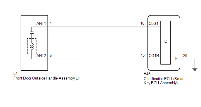
The certification ECU (smart key ECU assembly) generates a request signal and transmits the signal to the front door outside handle assembly LH (electrical key antenna) at intervals of 0.25 seconds. For the front door outside handle assembly LH (electrical key antenna) to detect when the electrical key transmitter sub-assembly is brought close to the vehicle, a signal requesting a response from the electrical key transmitter sub-assembly is transmitted within approximately 1 m (3.28 ft.) of the driver door at intervals of 0.25 seconds. DTC B27A113 is stored by the certification ECU (smart key ECU assembly) when an open is detected between the certification ECU (smart key ECU assembly) and front door outside handle assembly LH (electrical key antenna) (between terminals CLG1 and ANT1, or terminals CG1B and ANT2).
| DTC No. | Detection Item | DTC Detection Condition | Trouble Area | Note |
|---|---|---|---|---|
| B27A113 | Driver Side Electrical Antenna Circuit Open | An open is detected in the circuit between the certification ECU (smart key ECU assembly) and front door outside handle assembly LH (CLG1 - ANT1, CG1B - ANT2) (This is detected by the malfunction detection circuit in the certification ECU (smart key ECU assembly)) (1 trip detection logic*). |
|
|
- *: Only output while a malfunction is present.
| Vehicle Condition when Malfunction Detected | Fail-safe Operation when Malfunction Detected |
|---|---|
| Entry lock/unlock operation cannot be performed for driver door | - |
| DTC No. | Data List and Active Test |
|---|---|
| B27A113 | Key diagnostic mode can be used to perform troubleshooting |
WIRING DIAGRAM
CAUTION / NOTICE / HINT
NOTICE:
- When using the GTS with the ignition switch off, connect the GTS to the DLC3 and turn a courtesy light switch on and off at intervals of 1.5 seconds or less until communication between the GTS and the vehicle begins. Then select the vehicle type under manual mode and enter the following menus: Body Electrical / Smart Key. While using the GTS, periodically turn a courtesy light switch on and off at intervals of 1.5 seconds or less to maintain communication between the GTS and the vehicle.
-
The smart key system (for Entry Function) uses the CAN communication system. Inspect the communication function by following How to Proceed with Troubleshooting. Troubleshoot the smart key system (for Entry Function) after confirming that the communication systems are functioning properly.
Click here

-
Before replacing the certification ECU (smart key ECU assembly), refer to Precaution.
Click here

- After repair, confirm that no DTCs are output by performing "DTC Output Confirmation Operation".
PROCEDURE
| 1. | CHECK CONNECTOR CONNECTION |
(a) Check that the connectors are properly connected to the certification ECU (smart key ECU assembly) and front door outside handle assembly LH.
OK:
Connectors are properly connected.
| NG |
 | CONNECT CONNECTORS PROPERLY |
|

| 2. | CHECK HARNESS AND CONNECTOR (CERTIFICATION ECU (SMART KEY ECU ASSEMBLY) - FRONT DOOR OUTSIDE HANDLE ASSEMBLY LH) |
(a) Disconnect the H46 certification ECU (smart key ECU assembly) connector.
(b) Disconnect the L4 front door outside handle assembly LH connector.
(c) Measure the resistance according to the value(s) in the table below.
Standard Resistance:
| Tester Connection | Condition | Specified Condition |
|---|---|---|
| H46-16 (CLG1) - L4-4 (ANT1) | Always | Below 1 Ω |
| H46-15 (CG1B) - L4-6 (ANT2) | Always | Below 1 Ω |
(d) Reconnect the H46 certification ECU (smart key ECU assembly) connector.
| NG |
 | REPAIR OR REPLACE HARNESS OR CONNECTOR |
|

| 3. | CHECK CERTIFICATION ECU (SMART KEY ECU ASSEMBLY) (OUTPUT TO FRONT DOOR OUTSIDE HANDLE ASSEMBLY LH) |
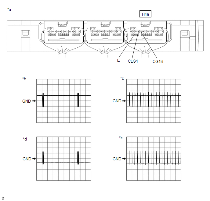
| *a | Component with harness connected (Certification ECU (Smart Key ECU Assembly)) | *b | Waveform 1 |
| *c | Waveform 2 | *d | Waveform 3 |
| *e | Waveform 4 | - | - |
(a) Using an oscilloscope, check the waveform.
OK:
| Tester Connection | Condition | Tool Setting | Specified Condition |
|---|---|---|---|
| H46-16 (CLG1) - H46-29 (E) | Procedure:
| 5 V/DIV., 500 ms./DIV. | Pulse generation (See waveform 1) |
| Procedure:
| 5 V/DIV., 500 ms./DIV. | Pulse generation (See waveform 2) | |
| H46-15 (CG1B) - H46-29 (E) | Procedure:
| 5 V/DIV., 500 ms./DIV. | Pulse generation (See waveform 3) |
| Procedure:
| 5 V/DIV., 500 ms./DIV. | Pulse generation (See waveform 4) |
-
*: For details about the entry function detection area, refer to Operation Check.
Click here

| OK |
 | REPLACE FRONT DOOR OUTSIDE HANDLE ASSEMBLY LH |
| NG |
 | REPLACE CERTIFICATION ECU (SMART KEY ECU ASSEMBLY) |

 Front Passenger Side Electrical Antenna Circuit Open (B27A213)
DESCRIPTION The certification ECU (smart key ECU assembly) generates a request signal and transmits the signal to the front door outside handle assembly RH (electrical key antenna) at intervals of 0...
Other information:
Toyota Yaris XP210 (2020-2026) Reapir and Service Manual: Data List / Active Test
DATA LIST / ACTIVE TEST DATA LIST NOTICE: Some Data List values may vary significantly due to slight measurement errors, differences in the measurement environment, and changes in the vehicle over time, making it difficult to indicate clear evaluation standards...
Toyota Yaris XP210 (2020-2026) Reapir and Service Manual: Removal
REMOVAL PROCEDURE 1. REMOVE NO. 1 INSTRUMENT PANEL UNDER COVER SUB-ASSEMBLY Click here 2. REMOVE STOP LIGHT SWITCH ASSEMBLY (a) Disconnect the connector. (b) Remove the stop light switch assembly as shown in the illustration. Remove in this Direction 3...
Categories
- Manuals Home
- Toyota Yaris Owners Manual
- Toyota Yaris Service Manual
- Power Integration No.1 System Missing Message (B235287,B235587,B235787-B235987)
- Key Battery Replacement
- How to connect USB port/Auxiliary jack
- New on site
- Most important about car
Key Suspend Function
If a key is left in the vehicle, the functions of the key left in the vehicle are temporarily suspended to prevent theft of the vehicle.
To restore the functions, press the unlock button on the functions-suspended key in the vehicle.