
Toyota Yaris: Before Driving / Driving Tips
Toyota Yaris XP210 (2020-2026) Owner's Manual / Before Driving / Driving Tips
- Break-In Period
- Saving Fuel and Protection of the Environment
- Hazardous Driving
- Floor Mat
- Rocking the Vehicle
- Winter Driving
- Driving In Flooded Area
- Overloading
- Driving on Uneven Road
 To Stop the Alarm
A triggered alarm can be turned off using any one of the following
methods:
Pressing the unlock button or the trunk button (4-door) on the smart
key...
 Break-In Period
No special break-in is necessary, but a few precautions in the first 600
miles (1,000 km) may add to the performance, economy, and life of
the vehicle...
Other information:
Toyota Yaris XP210 (2020-2026) Owner's Manual: Basic Operation Method
TOUCH & TAP Touch or tap on the item indicated on the screen. The operation is launched and the next item is displayed. SLIDE Touch the setting item displaying a slider bar. Touch the slider with your finger and move to the desired level...
Toyota Yaris XP210 (2020-2026) Reapir and Service Manual: Problem Symptoms Table
PROBLEM SYMPTOMS TABLE NOTICE: Before replacing the main body ECU (multiplex network body ECU) or certification ECU (smart key ECU assembly), refer to Registration. Click here HINT: Use the table below to help determine the cause of problem symptoms...
Categories
- Manuals Home
- Toyota Yaris Owners Manual
- Toyota Yaris Service Manual
- Removal
- To Set Speed
- G16e-gts (engine Mechanical)
- New on site
- Most important about car
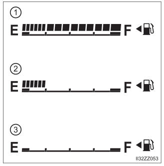
Fuel Gauge
The fuel gauge shows approximately how much fuel is remaining in the tank when the ignition is switched ON. We recommend keeping the tank over 1/4 full.

Copyright © 2026 www.toyaris4.com