
Toyota Yaris: Front Brake / Disassembly
DISASSEMBLY
PROCEDURE
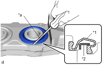
1. REMOVE CYLINDER BOOT
| (a) Using a screwdriver with its tip wrapped with protective tape, remove the 4 cylinder boots from the front disc brake cylinder. NOTICE:
|
|
2. REMOVE FRONT DISC BRAKE PISTON
| (a) Install a wooden block between the pistons of the front disc brake cylinder to stop them coming out. |
|
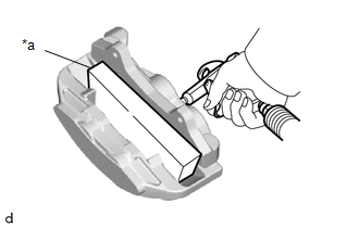
(b) Using an air gun, gradually apply compressed air until the 4 front disc brake pistons touch the wooden block.
CAUTION:
-
Do not insert your hand between the pistons to hold the front disc brake cylinder.
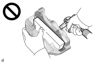
- When compressed air is blown in, the front disc brake piston may jump out quickly and trap your fingers.
NOTICE:
Do not allow any brake fluid to spatter.
(c) Remove the wooden block.
| (d) Remove the 4 front disc brake pistons from the front disc brake cylinder. |
|
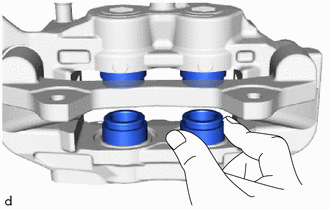
3. REMOVE PISTON SEAL
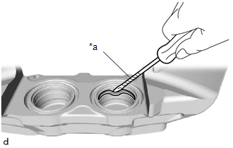
| (a) Using a screwdriver with its tip wrapped with protective tape, remove the 4 piston seals from the front disc brake cylinder. NOTICE: Do not damage the cylinder bore and the seal groove. |
|
4. REMOVE FRONT DISC BRAKE BLEEDER PLUG CAP
(a) Remove the front disc brake bleeder plug cap from the front disc brake bleeder plug.
5. REMOVE FRONT DISC BRAKE BLEEDER PLUG
(a) Remove the front disc brake bleeder plug from the front disc brake cylinder.
 Components
COMPONENTS ILLUSTRATION
*1 FRONT DISC BRAKE PIN HOLD CLIP *2 FRONT DISC BRAKE ANTI-RATTLE PIN *3 FRONT DISC BRAKE ANTI-RATTLE SPRING *4 FRONT DISC BRAKE PAD *5 FRONT DISC BRAKE ANTI-SQUEAL SHIM - - ILLUSTRATION
*1 FRONT FLEXIBLE HOSE *2 UNION BOLT *3 GASKET *4 FRONT DISC BRAKE CYLINDER ASSEMBLY *5 FRONT DISC - -
Tightening torque for "Major areas involving basic vehicle performance such as moving/turning/stopping": N*m (kgf*cm, ft...
 Removal
REMOVAL CAUTION / NOTICE / HINT NOTICE:
To avoid degrading the precision of the assembly, do not loosen or remove the 2 bolts shown in the illustration...
Other information:
Toyota Yaris XP210 (2020-2026) Reapir and Service Manual: Vehicle Control History
VEHICLE CONTROL HISTORY CHECK VEHICLE CONTROL HISTORY HINT: The vehicle control history data stores the history of the reject function and system protection operations. The number of occurrences, date and distance are stored in batches for each item...
Toyota Yaris XP210 (2020-2026) Reapir and Service Manual: Data List / Active Test
DATA LIST / ACTIVE TEST DATA LIST HINT: Using the GTS to read the Data List allows the values or states of switches, sensors, actuators and other items to be read without removing any parts. This non-intrusive inspection can be very useful because intermittent conditions or signals may be discovered before parts or wiring is disturbed...
Categories
- Manuals Home
- Toyota Yaris Owners Manual
- Toyota Yaris Service Manual
- Engine & Hybrid System
- Maintenance
- How to use USB mode
- New on site
- Most important about car
Front Seat Belt Pretensioners
The front seat belt pretensioners are designed to deploy in moderate or severe frontal, near frontal collisions.
In addition, the pretensioners operate when a side collision or a rollover accident is detected. The pretensioners operate differently depending on what types of air bags are equipped. For more details about the seat belt pretensioner operation, refer to the SRS Air Bag Deployment Criteria.
