Toyota Yaris: Front Brake / Removal
REMOVAL
CAUTION / NOTICE / HINT
NOTICE:
-
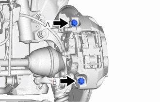
To avoid degrading the precision of the assembly, do not loosen or remove the 2 bolts shown in the illustration.
-
If the bolts have been loosened or removed, use the following procedure to reassemble the parts.
- Temporarily install the front disc brake cylinder assembly with the 2 bolts.
- Start the engine.
- Depress the brake pedal to continuously apply hydraulic pressure.
- Temporarily tighten bolt A to 30 N*m (306 kgf*cm, 22 ft.*lbf).
- Temporarily tighten bolt B to 30 N*m (306 kgf*cm, 22 ft.*lbf).
- Fully tighten bolt A to 100 N*m (1020 kgf*cm, 74 ft.*lbf).
- Fully tighten bolt B to 100 N*m (1020 kgf*cm, 74 ft.*lbf).
- Release the brake pedal to release the hydraulic pressure.
- Check that the 2 bolts are tightened to 100 N*m (1020 kgf*cm, 74 ft.*lbf).
HINT:
- Use the same procedure for the RH side and LH side.
- The following procedure is for the LH side.
PROCEDURE
1. REMOVE FRONT WHEEL
Click here

2. DRAIN BRAKE FLUID
NOTICE:
If brake fluid leaks onto any painted surface, immediately wash it off.
3. REMOVE FRONT DISC BRAKE PIN HOLD CLIP
Click here

4. REMOVE FRONT DISC BRAKE ANTI-RATTLE PIN
Click here

5. REMOVE FRONT DISC BRAKE ANTI-RATTLE SPRING
Click here

6. REMOVE FRONT DISC BRAKE PAD
Click here

7. REMOVE FRONT DISC BRAKE ANTI-SQUEAL SHIM KIT
Click here

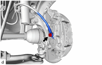
8. DISCONNECT FRONT FLEXIBLE HOSE
| (a) Remove the union bolt and gasket, and disconnect the front flexible hose from the front disc brake cylinder assembly. |
|
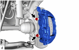
9. REMOVE FRONT DISC BRAKE CYLINDER ASSEMBLY
| (a) Remove the 2 bolts and front disc brake cylinder assembly from the steering knuckle. |
|
10. REMOVE FRONT DISC
| (a) Put matchmarks on the front disc and the front axle hub sub-assembly. HINT: Not required when replacing the front disc. |
|
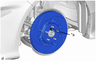
(b) Remove the front disc from the front axle hub sub-assembly.
 Disassembly
DISASSEMBLY PROCEDURE 1. REMOVE CYLINDER BOOT (a) Using a screwdriver with its tip wrapped with protective tape, remove the 4 cylinder boots from the front disc brake cylinder...
 Inspection
INSPECTION PROCEDURE 1. INSPECT BRAKE CYLINDER AND PISTON (a) Check the front disc brake cylinder bore and front disc brake piston for rust and scoring...
Other information:
Toyota Yaris XP210 (2020-2026) Reapir and Service Manual: Before Starting Driving Adjustment
BEFORE STARTING DRIVING ADJUSTMENT CAUTION / NOTICE / HINT HINT: Purpose of millimeter wave radar beam axis learning If the installation position or orientation of the millimeter wave radar sensor is changed due to it being removed and reinstalled or replaced with a new one, or due to the front bumper or radiator grille being replaced, it is necessary for the millimeter wave radar sensor to learn the driving direction of the vehicle in order for each driving support system to operate correctly...
Toyota Yaris XP210 (2020-2026) Owner's Manual: Uniform Tire Quality Grading System (UTQGS)
This information relates to the tire grading system developed by the U.S. National Highway Traffic Safety Administration for grading tires by tread wear, traction, and temperature performance. Tread Wear The tread wear grade is a comparative rating based on the wear rate of the tire when tested under controlled conditions on a specified government test course...
Categories
- Manuals Home
- Toyota Yaris Owners Manual
- Toyota Yaris Service Manual
- How to connect USB port/Auxiliary jack
- Fuel Gauge
- Removal
- New on site
- Most important about car
Keys

To use the auxiliary key, press the knob and pull out the auxiliary key from the smart key.
