Toyota Yaris: Vehicle Stability Control System / Brake Master Cylinder Pressure Sensor Supply Voltage Circuit Short to Ground or Open (C122D14)
DESCRIPTION
| DTC No. | Detection Item | DTC Detection Condition | Trouble Area | DTC Output from |
|---|---|---|---|---|
| C122D14 | Brake Master Cylinder Pressure Sensor Supply Voltage Circuit Short to Ground or Open | Master cylinder pressure sensor power supply voltage decrease occurs or history of voltage decrease exists, and defective master cylinder pressure sensor output continues for 1.2 seconds or more. |
| Brake |
WIRING DIAGRAM
Refer to DTC C137BA2.
Click here

CAUTION / NOTICE / HINT
NOTICE:
- Inspect the fuses for circuits related to this system before performing the following procedure.
-
After replacing the skid control ECU (brake actuator assembly), perform "Calibration".
Click here

PROCEDURE
| 1. | CHECK HARNESS AND CONNECTOR (+BS TERMINAL) |
| (a) Make sure that there is no looseness at the locking part and the connecting part of the connectors. OK: The connector is securely connected. |
|
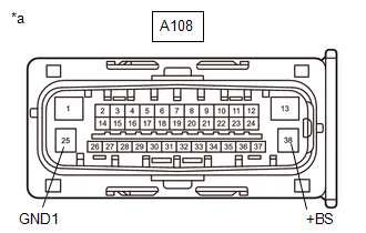
(b) Disconnect the A108 skid control ECU (brake actuator assembly) connector.
(c) Check both the connector case and the terminals for deformation and corrosion.
OK:
No deformation or corrosion.
(d) Measure the voltage according to the value(s) in the table below.
Standard Voltage:
| Tester Connection | Condition | Specified Condition |
|---|---|---|
| A108-38 (+BS) - Body ground | Always | 11 to 14 V |
| A108-38 (+BS) - A108-25 (GND1) | Always | 11 to 14 V |
| NG |
 | REPAIR OR REPLACE HARNESS OR CONNECTOR |
|

| 2. | CLEAR DTC |
(a) Reconnect the A108 skid control ECU (brake actuator assembly) connector.
(b) Operate the GTS to clear the codes.
Chassis > Brake > Clear DTCs(c) Press the DTC clear button.
(d) Turn the ignition switch off.
|

| 3. | RECONFIRM DTC |
(a) Operate the GTS to read the DTCs.
Chassis > Brake > Trouble Codes(b) Check if the same DTC is output.
| Result | Proceed to |
|---|---|
| C122D14 is not output | A |
| C122D14 is output | B |
| A |
 | USE SIMULATION METHOD TO CHECK |
| B |
 | REPLACE BRAKE ACTUATOR ASSEMBLY |
 Brake System Control Module "A" Internal Electronic Failure (C059749,...,C13C91C)
DESCRIPTION The solenoid relay and solenoid valves are built into the brake actuator assembly. The solenoid valves control the brake fluid pressure at each wheel cylinder...
 ECM Communication (C124A00)
DESCRIPTION DTC No. Detection Item DTC Detection Condition Trouble Area DTC Output from C124A00 ECM Communication Any of the following is detected:
The engine type, powertrain variation, engine stop and start ECU availability and destination information sent from the ECM do not match the information stored in the skid control ECU (brake actuator assembly)...
Other information:
Toyota Yaris XP210 (2020-2025) Reapir and Service Manual: Room Light
ComponentsCOMPONENTS ILLUSTRATION *1 NO. 1 ROOM LIGHT ASSEMBLY *2 NO. 1 ROOM LIGHT BULB *3 NO. 1 ROOM LIGHT LENS *4 NO. 1 ROOM LIGHT HOUSING RemovalREMOVAL PROCEDURE 1. REMOVE NO. 1 ROOM LIGHT ASSEMBLY (a) Using a screwdriver with its tip wrapped in protective tape, disengage the claws to remove the No...
Toyota Yaris XP210 (2020-2025) Reapir and Service Manual: Brake Pressure Sensor "A" Circuit Voltage Above Threshold (C054017)
DESCRIPTION DTC No. Detection Item DTC Detection Condition Trouble Area DTC Output from C054017 Brake Pressure Sensor "A" Circuit Voltage Above Threshold When vehicle speed exceeds 3 km/h (2 mph) and stop light switch assembly is OFF, master cylinder pressure continuously exceeds 1...
Categories
- Manuals Home
- Toyota Yaris Owners Manual
- Toyota Yaris Service Manual
- How to connect USB port/Auxiliary jack
- Fuel Gauge
- Engine Start Function When Key Battery is Dead
- New on site
- Most important about car
Front Seat Belt Pretensioners
The front seat belt pretensioners are designed to deploy in moderate or severe frontal, near frontal collisions.
In addition, the pretensioners operate when a side collision or a rollover accident is detected. The pretensioners operate differently depending on what types of air bags are equipped. For more details about the seat belt pretensioner operation, refer to the SRS Air Bag Deployment Criteria.